- 您現(xiàn)在的位置:買(mǎi)賣(mài)IC網(wǎng) > PDF目錄383959 > TMC22153AKHC (FAIRCHILD SEMICONDUCTOR CORP) JT 32C 32#20 SKT PLUG PDF資料下載
參數(shù)資料
| 型號(hào): | TMC22153AKHC |
| 廠商: | FAIRCHILD SEMICONDUCTOR CORP |
| 元件分類(lèi): | 顏色信號(hào)轉(zhuǎn)換 |
| 英文描述: | JT 32C 32#20 SKT PLUG |
| 中文描述: | COLOR SIGNAL DECODER, PQFP100 |
| 封裝: | MQFP-100 |
| 文件頁(yè)數(shù): | 69/84頁(yè) |
| 文件大小: | 417K |
| 代理商: | TMC22153AKHC |
第1頁(yè)第2頁(yè)第3頁(yè)第4頁(yè)第5頁(yè)第6頁(yè)第7頁(yè)第8頁(yè)第9頁(yè)第10頁(yè)第11頁(yè)第12頁(yè)第13頁(yè)第14頁(yè)第15頁(yè)第16頁(yè)第17頁(yè)第18頁(yè)第19頁(yè)第20頁(yè)第21頁(yè)第22頁(yè)第23頁(yè)第24頁(yè)第25頁(yè)第26頁(yè)第27頁(yè)第28頁(yè)第29頁(yè)第30頁(yè)第31頁(yè)第32頁(yè)第33頁(yè)第34頁(yè)第35頁(yè)第36頁(yè)第37頁(yè)第38頁(yè)第39頁(yè)第40頁(yè)第41頁(yè)第42頁(yè)第43頁(yè)第44頁(yè)第45頁(yè)第46頁(yè)第47頁(yè)第48頁(yè)第49頁(yè)第50頁(yè)第51頁(yè)第52頁(yè)第53頁(yè)第54頁(yè)第55頁(yè)第56頁(yè)第57頁(yè)第58頁(yè)第59頁(yè)第60頁(yè)第61頁(yè)第62頁(yè)第63頁(yè)第64頁(yè)第65頁(yè)第66頁(yè)第67頁(yè)第68頁(yè)當(dāng)前第69頁(yè)第70頁(yè)第71頁(yè)第72頁(yè)第73頁(yè)第74頁(yè)第75頁(yè)第76頁(yè)第77頁(yè)第78頁(yè)第79頁(yè)第80頁(yè)第81頁(yè)第82頁(yè)第83頁(yè)第84頁(yè)
PRODUCT SPECIFICATION
TMC22x5yA
REV. 1.0.0 2/4/03
69
Table 25. Serial Port Addresses
Data Transfer via Serial Interface
For each byte of data read or written, the MSB is the first bit;
that is, bit 7 of the 8-bit sequence.
If the TMC22x5yA does not acknowledge the master device
during a write sequence, the SDA remains HIGH so the mas-
ter can generate a stop signal. If the master device does not
acknowledge the TMC22x5yA during a read sequence, the
Decoder interprets this as “end of data.” The SDA remains
HIGH so the master can generate a stop signal.
Writing data to specific control registers of the TMC22x5yA
requires that the 8-bit address of the control register of inter-
est be written after the slave address has been established.
This control register address is the base address for subse-
quent write operations. The base address autoincrements by
one for each byte of data written after the data byte intended
for the base address. If more bytes are transferred than there
are available addresses, the address will not increment and
remain at its maximum value of 3Fh. Any base address
higher than 3Fh will not produce an ACKnowledge signal.
Data are read from the control registers of the TMC22x5yA
in a similar manner. Reading requires two data transfer
operations:
The base address must be written with the R/W\ bit of the
slave address byte LOW to set up a sequential read
operation.
bit 7
A
6
(MSB)
1
1
1
1
1
1
1
1
bit 6
A
5
bit 5
A
4
bit 4
A
3
bit 3
A
2
(SA
2)
0
0
0
0
1
1
1
1
bit 2
A
1
(SA
1)
0
0
1
1
0
0
1
1
bit 1
A
0
(SA
0)
0
1
0
1
0
1
0
1
0
0
0
0
0
0
0
0
1
1
1
1
1
1
1
1
1
1
1
1
1
1
1
1
Reading (the R/W bit of the slave address byte HIGH)
begins at the previously established base address. The
address of the read register autoincrements after each byte is
transferred.
To terminate a write sequence to the TMC22x5yA, a stop
signal must be sent. A stop signal comprises a LOW-to-
HIGH transition of SDA while SCL is HIGH. To terminate a
read sequence simply do not acknowledge (NOACK) the last
byte received and the TMC22x5yA will terminate the
sequence.
A repeated start signal occurs when the master device driv-
ing the serial interface generates a start signal without first
generating a stop signal to terminate the current communica-
tion. This is used to change the mode of communication
(read, write) between the slave and master without releasing
the serial interface lines.
Serial Interface Read/Write Examples
Write to one control register
Start signal
Slave Address byte (R/W bit = LOW)
Block Pointer (00)
Base Address byte
Data byte to base address
Stop signal
Write to four consecutive XLUT locations
Start signal
Slave Address byte (R/W bit = LOW)
Block Pointer (01)
Base Address byte
Data byte to base address
Data byte to (base address + 1)
Data byte to (base address + 2)
Data byte to (base address + 3)
Stop signal
Read from one XLUT location
Start signal
Slave Address byte (R/W bit = LOW)
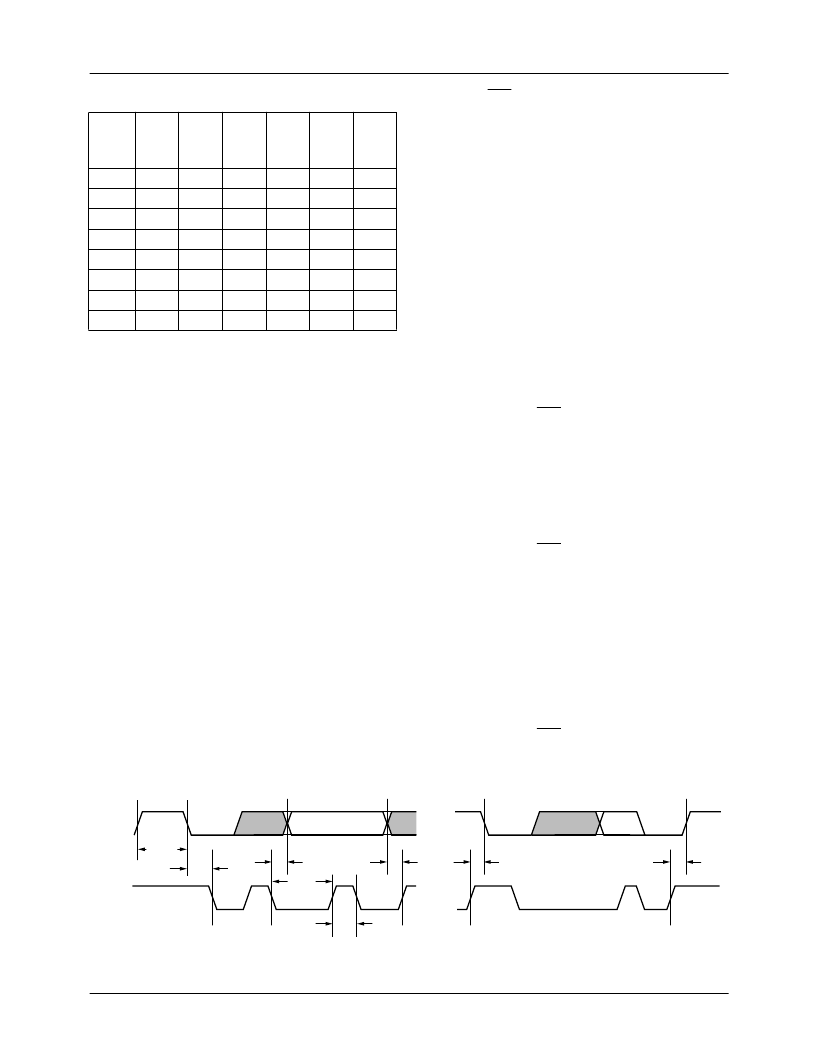
Figure 35. Serial Port Read/Write Timing
t
BUFF
t
STAH
t
STASU
t
STOSU
t
DHO
t
DSU
t
DAL
t
BAH
SCL
SDA
65-22x5y-18
相關(guān)PDF資料 |
PDF描述 |
|---|---|
| TMC3003R2C80 | Triple Video D/A Converter |
| TMC3003KRC30 | Triple Video D/A Converter |
| TMC3003KRC50 | Triple Video D/A Converter |
| TMC3003KRC80 | Triple Video D/A Converter |
| TMC3003 | Triple Video D/A Converter |
相關(guān)代理商/技術(shù)參數(shù) |
參數(shù)描述 |
|---|---|
| TMC22191 | 制造商:CADEKA 制造商全稱(chēng):CADEKA 功能描述:Digital Video Encoders/Layering Engine |
| TMC22191KHC | 功能描述:視頻 IC D/V Encoder Layering Engine RoHS:否 制造商:Fairchild Semiconductor 工作電源電壓:5 V 電源電流:80 mA 最大工作溫度:+ 85 C 封裝 / 箱體:TSSOP-28 封裝:Reel |
| TMC22191R0C | 功能描述:視頻 IC D/V Encoder Layering Engine RoHS:否 制造商:Fairchild Semiconductor 工作電源電壓:5 V 電源電流:80 mA 最大工作溫度:+ 85 C 封裝 / 箱體:TSSOP-28 封裝:Reel |
| TMC22191R0CT | 功能描述:視頻 IC D/V Encoder Layering Engine RoHS:否 制造商:Fairchild Semiconductor 工作電源電壓:5 V 電源電流:80 mA 最大工作溫度:+ 85 C 封裝 / 箱體:TSSOP-28 封裝:Reel |
| TMC222 | 制造商:Trinamic 功能描述:IC SM WITH I2C INTERFACE |
發(fā)布緊急采購(gòu),3分鐘左右您將得到回復(fù)。