- 您現(xiàn)在的位置:買賣IC網(wǎng) > PDF目錄383878 > TAS5036APFCRG4 (Texas Instruments, Inc.) Six Channel Digital Audio PWM Processor PDF資料下載
參數(shù)資料
| 型號(hào): | TAS5036APFCRG4 |
| 廠商: | Texas Instruments, Inc. |
| 英文描述: | Six Channel Digital Audio PWM Processor |
| 中文描述: | 六通道數(shù)字音頻PWM處理器 |
| 文件頁(yè)數(shù): | 15/62頁(yè) |
| 文件大小: | 790K |
| 代理商: | TAS5036APFCRG4 |
第1頁(yè)第2頁(yè)第3頁(yè)第4頁(yè)第5頁(yè)第6頁(yè)第7頁(yè)第8頁(yè)第9頁(yè)第10頁(yè)第11頁(yè)第12頁(yè)第13頁(yè)第14頁(yè)當(dāng)前第15頁(yè)第16頁(yè)第17頁(yè)第18頁(yè)第19頁(yè)第20頁(yè)第21頁(yè)第22頁(yè)第23頁(yè)第24頁(yè)第25頁(yè)第26頁(yè)第27頁(yè)第28頁(yè)第29頁(yè)第30頁(yè)第31頁(yè)第32頁(yè)第33頁(yè)第34頁(yè)第35頁(yè)第36頁(yè)第37頁(yè)第38頁(yè)第39頁(yè)第40頁(yè)第41頁(yè)第42頁(yè)第43頁(yè)第44頁(yè)第45頁(yè)第46頁(yè)第47頁(yè)第48頁(yè)第49頁(yè)第50頁(yè)第51頁(yè)第52頁(yè)第53頁(yè)第54頁(yè)第55頁(yè)第56頁(yè)第57頁(yè)第58頁(yè)第59頁(yè)第60頁(yè)第61頁(yè)第62頁(yè)
Architecture Overview
9
SLES061B—November 2002—Revised January 2004
TAS5036A
2.1.3.1
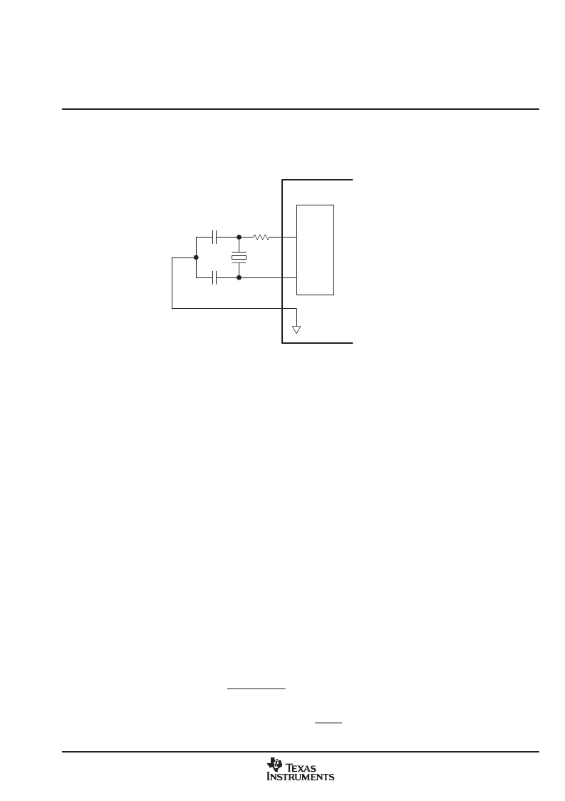
Crystal Type and Circuit
In clock master mode the TAS5036A can derive the MCLKOUT, SCLK, and LRCLK from a crystal. In this case,
the TAS5036A uses a parallel-mode fundamental crystal. This crystal is connected to the TAS5036A as shown
in Figure 21.
XO
TAS5036A
OSC
MACRO
rd
C1
XI
C2
AVSS
rd = Drive Level Control Resistor Crystal Vendor Specified
CL = Crystal Load Capacitance (Capacitance of Circuitry Between the Two Terminals of the Crystal)
CL = (C1
×
C2 )/(C1 + C2 ) + CS (Where CS = Board Stray Capacitance
≈
3 pF)
Example: Vendor-Recommended CL = 18 pF, CS = 3 pF
≥
C1 = C2 = 2
×
(183) = 30 pF
Figure 21. Crystal Circuit
2.1.4 Clock Slave Mode
In the slave mode (M_S = 0), the master clock, LRCLK, and SCLK are inputs to the TAS5036A. The master
clock is supplied through the MCLK_IN terminal.
As in the master mode, the TAS5036A device develops its internal timing from the internal phase-locked loop
(PLL). The reference clock for the PLL is provided by the input to the MCLK_IN terminal. This input is at a
frequency of 256 times (128 in quad mode) the input data rate. The SCLK frequency is 48 or 64 times the data
sample rate. The LRCLK frequency is the data sample rate. The TAS5036A does not require any specific
phase relationship between SRCLK and MCLK_IN, but there must be synchronization. The TAS5036A
monitors the relationship between MCLK, SCLK, and LRCLK. The TAS5036A detects if any of the three clocks
is absent, if the LRCLK rate changes more than 10 MCLK cycles since the last device reset or clock error, or
if the MCLK frequency is changing substantially with respect to the PLL frequency.
When a clock error is detected, the TAS5036A performs a clock error management sequence.
The clock error management sequence temporarily suspends processing, places the PWM outputs in a hard
mute (PWM_P outputs are low; PWM_M outputs are high, and all VALID signals are low), resets all internal
processes, sets the volumes to mute, and suspends all I
2
C operations.
When the error condition is corrected, the TAS5036A exits the clock error sequence by performing a partial
re-initialization, noiselessly restarting the PWM output, and ramping the volume up to the level specified in
the volume control registers. This sequence is performed over a 60-ms interval. The TAS5036A preserves
all control register settings that were set prior to the clock interruption.
If a clock error occurs while the ERR_RCVRY terminal is asserted (low), the TAS5036A performs the error
management sequence up to the unmute sequence. In this case, the volume remains at full attenuation with
the PWM output at a 50% duty cycle. The volume can be restored from this latched mute state by triggering
a mute/unmute sequence by asserting and releasing MUTE either by using the terminal, the system control
register 0x01 D4, or the individual channel mute register D5D0.
相關(guān)PDF資料 |
PDF描述 |
|---|---|
| TAS5036B_06 | Six Channel Digital Audio PWM Processor |
| TAS5036BPFCG4 | Six Channel Digital Audio PWM Processor |
| TAS5036BPFCR | Six Channel Digital Audio PWM Processor |
| TAS5036BPFCRG4 | Six Channel Digital Audio PWM Processor |
| TAS5100ADAP | Single Audio Amplifier |
相關(guān)代理商/技術(shù)參數(shù) |
參數(shù)描述 |
|---|---|
| TAS5036B | 制造商:TI 制造商全稱:Texas Instruments 功能描述:Six Channel Digital Audio PWM Precessor |
| TAS5036B_06 | 制造商:TI 制造商全稱:Texas Instruments 功能描述:Six Channel Digital Audio PWM Processor |
| TAS5036BPFC | 功能描述:音頻 DSP Dig Aud PWM Proc RoHS:否 制造商:Texas Instruments 工作電源電壓: 電源電流: 工作溫度范圍: 安裝風(fēng)格: 封裝 / 箱體: 封裝:Tube |
| TAS5036BPFCG4 | 功能描述:音頻 DSP Dig Aud PWM Proc RoHS:否 制造商:Texas Instruments 工作電源電壓: 電源電流: 工作溫度范圍: 安裝風(fēng)格: 封裝 / 箱體: 封裝:Tube |
| TAS5036BPFCR | 功能描述:多媒體雜項(xiàng) Dig Aud PWM Proc RoHS:否 制造商:Texas Instruments 類型: 通道數(shù)量: 轉(zhuǎn)換速率:540 Mbps 分辨率: 封裝 / 箱體:SOIC-16 封裝:Tube |
發(fā)布緊急采購(gòu),3分鐘左右您將得到回復(fù)。