- 您現(xiàn)在的位置:買賣IC網(wǎng) > PDF目錄383844 > STPCD01 STPC CLIENT DATASHEET / PC COMPATIBLE EMBEDED MICROPROCESSOR PDF資料下載
參數(shù)資料
| 型號: | STPCD01 |
| 英文描述: | STPC CLIENT DATASHEET / PC COMPATIBLE EMBEDED MICROPROCESSOR |
| 中文描述: | STPC客戶部件/ PC兼容的嵌入式微處理器 |
| 文件頁數(shù): | 32/61頁 |
| 文件大?。?/td> | 1007K |
| 代理商: | STPCD01 |
第1頁第2頁第3頁第4頁第5頁第6頁第7頁第8頁第9頁第10頁第11頁第12頁第13頁第14頁第15頁第16頁第17頁第18頁第19頁第20頁第21頁第22頁第23頁第24頁第25頁第26頁第27頁第28頁第29頁第30頁第31頁當(dāng)前第32頁第33頁第34頁第35頁第36頁第37頁第38頁第39頁第40頁第41頁第42頁第43頁第44頁第45頁第46頁第47頁第48頁第49頁第50頁第51頁第52頁第53頁第54頁第55頁第56頁第57頁第58頁第59頁第60頁第61頁
ELECTRICAL SPECIFICATIONS
32/61
Issue 2.2 - October 13, 2000
4. ELECTRICAL SPECIFICATIONS
4.1 INTRODUCTION
The electrical specifications in this chapter are val-
id for the STPC Client.
4.2 ELECTRICAL CONNECTIONS
4.2.1 POWER/GROUND CONNECTIONS/
DECOUPLING
Due to the high frequency of operation of the
STPC Client, it is necessary to install and test this
device using standard high frequency techniques.
The high clock frequencies used in the STPC Cli-
ent and its output buffer circuits can cause tran-
sient power surges when several output buffers
switch output levels simultaneously. These effects
can be minimized by filtering the DC power leads
with low-inductance decoupling capacitors, using
low impedance wiring, and by utilizing all of the
VSS and VDD pins.
4.2.2 UNUSED INPUT PINS
All inputs not used by the designer and not listed
in the table of pin connections in Chapter 3 should
be connected either to VDD or to VSS. Connect
active-high inputs to VDD through a 20 k
(±10%)
pull-down resistor and active-low inputs to VSS
and connect active-low inputs to VCC through a
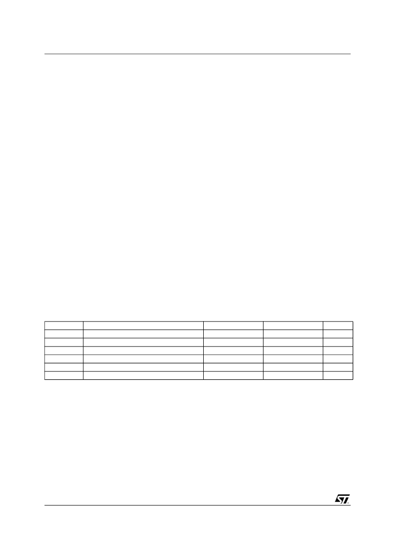
Table 4-1. Absolute Maximum Ratings
20 k
(±10%) pull-up resistor to prevent spurious
operation.
4.2.3 RESERVED DESIGNATED PINS
Pins designated reserved should be left discon-
nected. Connecting a reserved pin to a pull-up re-
sistor, pull-down resistor, or an active signal could
cause unexpected results and possible circuit
malfunctions.
4.3 ABSOLUTE MAXIMUM RATINGS
The following table lists the absolute maximum
ratings for the STPC Client device. Stresses be-
yond those listed under
Table 4-1
limits may
cause permanent damage to the device. These
are stress ratings only and do not imply that oper-
ation under any conditions other than those spec-
ified in section "Operating Conditions".
Exposure to conditions beyond
Table 4-1
may (1)
reduce device reliability and (2) result in prema-
ture failure even when there is no immediately ap-
parent sign of failure. Prolonged exposure to con-
ditions at or near the absolute maximum ratings
(
Table 4-1
) may also result in reduced useful life
and reliability.
Note 1 : -40
°C limit of T
CASE
(extended temperature
range) is given a s a preliminary specification and so as
all the -40°C related data.
Symbol
V
DDx
V
I
, V
O
V
5T
V
ESD
T
CASE
P
TOT
Parameter
Minimum
-0.3
-0.3
2.5
1500
-40
-
Maximum
4.0
VDD + 0.3
5.5
V
+115
4.8
Units
V
V
V
DC Supply Voltage
Digital Input and Output Voltage
5Volt Tolerance
ESD Capacity (Human body mode)
Operating Case Temperature (Note 1)
Total Power Dissipation
°C
W
相關(guān)PDF資料 |
PDF描述 |
|---|---|
| STPCD0110BTC3 | 32-Bit Microprocessor |
| STPCD0112BTC3 | 32-Bit Microprocessor |
| STPCD0113BTC3 | 32-Bit Microprocessor |
| STPCI01 | STPC INDUSTRIAL / PC COMPATIBLE EMBEDED MICROPROCESSOR |
| STPCI2 | STPC ATLAS DATASHEET / X86 CORE PC COMPATIBLE SYSTEM-ON-CHIP FOR TERMINALS |
相關(guān)代理商/技術(shù)參數(shù) |
參數(shù)描述 |
|---|---|
| STPCD0110BTC3 | 制造商:未知廠家 制造商全稱:未知廠家 功能描述:32-Bit Microprocessor |
| STPCD0112BTC3 | 制造商:未知廠家 制造商全稱:未知廠家 功能描述:32-Bit Microprocessor |
| STPCD0113BTC3 | 制造商:未知廠家 制造商全稱:未知廠家 功能描述:32-Bit Microprocessor |
| STPCD0166BTA3 | 制造商:STMICROELECTRONICS 制造商全稱:STMicroelectronics 功能描述:PC Compatible Embedded Microprocessor |
| STPCD0166BTC3 | 制造商:STMicroelectronics 功能描述:MPU STPC RISC 64-Bit 66MHz 388-Pin BGA |
發(fā)布緊急采購,3分鐘左右您將得到回復(fù)。