- 您現(xiàn)在的位置:買賣IC網(wǎng) > PDF目錄383837 > ST16C580 (Exar Corporation) UART WITH 16-BYTE FIFO’s AND INFRARED (IrDA) ENCODER/DECODER PDF資料下載
參數(shù)資料
| 型號(hào): | ST16C580 |
| 廠商: | Exar Corporation |
| 英文描述: | UART WITH 16-BYTE FIFO’s AND INFRARED (IrDA) ENCODER/DECODER |
| 中文描述: | UART的16字節(jié)FIFO的和紅外線(IrDA)編碼/解碼器 |
| 文件頁數(shù): | 22/41頁 |
| 文件大?。?/td> | 244K |
| 代理商: | ST16C580 |
第1頁第2頁第3頁第4頁第5頁第6頁第7頁第8頁第9頁第10頁第11頁第12頁第13頁第14頁第15頁第16頁第17頁第18頁第19頁第20頁第21頁當(dāng)前第22頁第23頁第24頁第25頁第26頁第27頁第28頁第29頁第30頁第31頁第32頁第33頁第34頁第35頁第36頁第37頁第38頁第39頁第40頁第41頁

ST16C580
22
Rev. 1.20
LCR BIT-4:
If the parity bit is enabled with LCR bit-3 set to a logic
1, LCR BIT-4 selects the even or odd parity format.
Logic 0 = ODD Parity is generated by forcing an odd
number of logic 1’s in the transmitted data. The
receiver must be programmed to check the same
format. (normal default condition)
Logic 1 = EVEN Parity
is generated by forcing an even
the number of logic 1’s in the transmitted. The receiver
must be programmed to check the same format.
LCR BIT-5:
If the parity bit is enabled, LCR BIT-5 selects the
forced parity format.
LCR BIT-5 = logic 0, parity is not forced (normal
default condition)
LCR BIT-5 = logic 1 and LCR BIT-4 = logic 0, parity bit
is forced to a logical 1 for the transmit and receive
data.
LCR BIT-5 = logic 1 and LCR BIT-4 = logic 1, parity bit
is forced to a logical 0 for the transmit and receive
data.
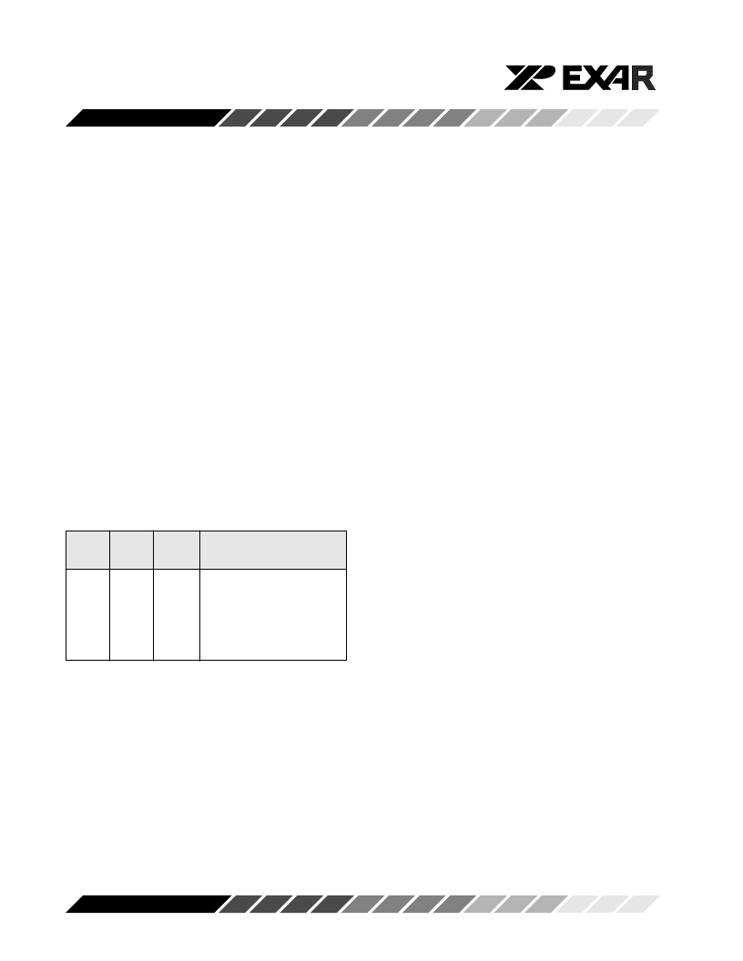
LCR
Bit-5
LCR
Bit-4
LCR
Bit-3
Parity selection
X
0
0
1
1
X
0
1
0
1
0
1
1
1
1
No parity
Odd parity
Even parity
Force parity “1”
Forced parity “0”
LCR BIT-6:
When enabled the Break control bit causes a break
condition to be transmitted (the TX output is forced to
a logic 0 state). This condition exists until disabled by
setting LCR bit-6 to a logic 0.
Logic 0 = No TX break condition. (normal default
condition)
Logic 1 = Forces the transmitter output (TX) to a logic
0 for alerting the remote receiver to a line break
condition.
LCR BIT-7:
The internal baud rate counter latch and Enhance
Feature mode enable.
Logic 0 = Divisor latch disabled. (normal default
condition)
Logic 1 = Divisor latch and enhanced feature register
enabled.
Modem Control Register (MCR)
This register controls the interface with the modem or
a peripheral device.
MCR BIT-0:
Logic 0 = Force -DTR output to a logic 1. (normal
default condition)
Logic 1 = Force -DTR output to a logic 0.
MCR BIT-1:
Logic 0 = Force -RTS output to a logic 1. (normal
default condition)
Logic 1 = Force -RTS output to a logic 0.
Automatic RTS may be used for hardware flow control
by enabling EFR bit-6 (See EFR bit-6).
MCR BIT-2:
Logic 0 = Set -OP1 output to a logic 1. (normal default
condition)
Logic 1 = Set -OP1 output to a logic 0.
MCR BIT-3:
Logic 0 = Set -OP2 output to a logic 1. (normal default
condition)
Logic 1 = Set -OP2 output to a logic 0.
MCR BIT-4:
Logic 0 = Disable loop-back mode. (normal default
condition)
Logic 1 = Enable local loop-back mode (diagnostics).
MCR BIT-5:
Not used.
MCR BIT-6:
Logic 0 = Enable Modem receive and transmit input/
output interface. (normal default condition)
Logic 1 = Enable infrared IrDA receive and transmit
相關(guān)PDF資料 |
PDF描述 |
|---|---|
| ST16C580CQ48 | UART WITH 16-BYTE FIFO’s AND INFRARED (IrDA) ENCODER/DECODER |
| ST16C580IJ44 | UART WITH 16-BYTE FIFO’s AND INFRARED (IrDA) ENCODER/DECODER |
| ST16C580IP40 | UART WITH 16-BYTE FIFO’s AND INFRARED (IrDA) ENCODER/DECODER |
| ST16C580IQ48 | UART WITH 16-BYTE FIFO’s AND INFRARED (IrDA) ENCODER/DECODER |
| ST16C580CP40 | Linear Voltage Regulator IC; Output Current Max:350mA; Supply Voltage Max:6V; Package/Case:8-TSSOP; Output Current:350mA; Output Voltage:3.3V; Current Rating:30.05A; Leaded Process Compatible:No; Output Voltage Max:3.3V |
相關(guān)代理商/技術(shù)參數(shù) |
參數(shù)描述 |
|---|---|
| ST16C580_05 | 制造商:EXAR 制造商全稱:EXAR 功能描述:UART WITH 16-BYTE FIFO’s AND INFRARED (IrDA) ENCODER/DECODER |
| ST16C580CJ44 | 制造商:EXAR 制造商全稱:EXAR 功能描述:UART WITH 16-BYTE FIFO’s AND INFRARED (IrDA) ENCODER/DECODER |
| ST16C580CP40 | 制造商:EXAR 制造商全稱:EXAR 功能描述:UART WITH 16-BYTE FIFO’s AND INFRARED (IrDA) ENCODER/DECODER |
| ST16C580CQ-0A-EVB | 功能描述:界面開發(fā)工具 Supports C580 48 ld TQFP, ISA Interface RoHS:否 制造商:Bourns 產(chǎn)品:Evaluation Boards 類型:RS-485 工具用于評(píng)估:ADM3485E 接口類型:RS-485 工作電源電壓:3.3 V |
| ST16C580CQ48 | 制造商:Rochester Electronics LLC 功能描述: 制造商:Exar Corporation 功能描述: |
發(fā)布緊急采購,3分鐘左右您將得到回復(fù)。