- 您現(xiàn)在的位置:買賣IC網(wǎng) > PDF目錄383837 > ST16C550 (Exar Corporation) UART with 16-Byte FIFO(通用異步接收器/發(fā)送器(帶16字節(jié)的先進先出)) PDF資料下載
參數(shù)資料
| 型號: | ST16C550 |
| 廠商: | Exar Corporation |
| 英文描述: | UART with 16-Byte FIFO(通用異步接收器/發(fā)送器(帶16字節(jié)的先進先出)) |
| 中文描述: | 的UART具有16字節(jié)FIFO(通用異步接收器/發(fā)送器(帶16字節(jié)的先進先出)) |
| 文件頁數(shù): | 11/36頁 |
| 文件大小: | 235K |
| 代理商: | ST16C550 |
第1頁第2頁第3頁第4頁第5頁第6頁第7頁第8頁第9頁第10頁當前第11頁第12頁第13頁第14頁第15頁第16頁第17頁第18頁第19頁第20頁第21頁第22頁第23頁第24頁第25頁第26頁第27頁第28頁第29頁第30頁第31頁第32頁第33頁第34頁第35頁第36頁
ST16C550
11
Rev. 4.20
DMA Operation
The ST16C550 FIFO trigger level provides additional
flexibility to the user for block mode operation. The user
can optionally operate the transmit and receive FIFO’s
in the DMA mode (FCR bit-3). The DMA mode affects
the state of the -RXRDY and -TXRDY output pins. The
following tables show this:
-RXRDY pin:
Non-DMA mode
1 = FIFO empty
DMA mode
0 to 1 transition when FIFO
empties
1 to 0 transition when FIFO
reaches trigger level, or
timeout occurs
0 = at least 1 byte
in FIFO
-TXRDY pin:
Non-DMA mode
1 = at least 1 byte
in FIFO
0 = FIFO empty
DMA mode
1 = FIFO is full
0 = FIFO has at least 1
empty location
Loop-back Mode
The internal loop-back capability allows onboard diag-
nostics. In the loop-back mode the normal modem
interface pins are disconnected and reconfigured for
loop-back internally. In this mode MSR bits 4-7 are
also disconnected. However, MCR register bits 0-3
can be used for controlling loop-back diagnostic test-
ing. In the loop-back mode -OP1 and -OP2 in the MCR
register (bits 0-1) control the modem -RI and -CD
inputs respectively. MCR signals -DTR and -RTS (bits
0-1) are used to control the modem -CTS and -DSR
inputs respectively. The transmitter output (TX) and the
receiver input (RX) are disconnected from their associ-
ated interface pins, and instead are connected together
internally (See Figure 4). The -CTS, -DSR, -CD, and -RI
are disconnected from their normal modem control
inputs pins, and instead are connected internally to -
DTR, -RTS, -OP1 and -OP2. Loop-back test data is
entered into the transmit holding register via the user
data bus interface, D0-D7. The transmit UART serial-
izes the data and passes the serial data to the receive
UART via the nternal oop-back connection. The receive
UART converts the serial data back into parallel data
that is then made available at the user data interface,
D0-D7. The user optionally compares the received data
to the initial transmitted data for verifying error free
operation of the UART TX/RX circuits.
In this mode , the receiver and transmitter interrupts are
fully operational. The Modem Control Interrupts are also
operational. The interrupts are still controlled by the
IER.
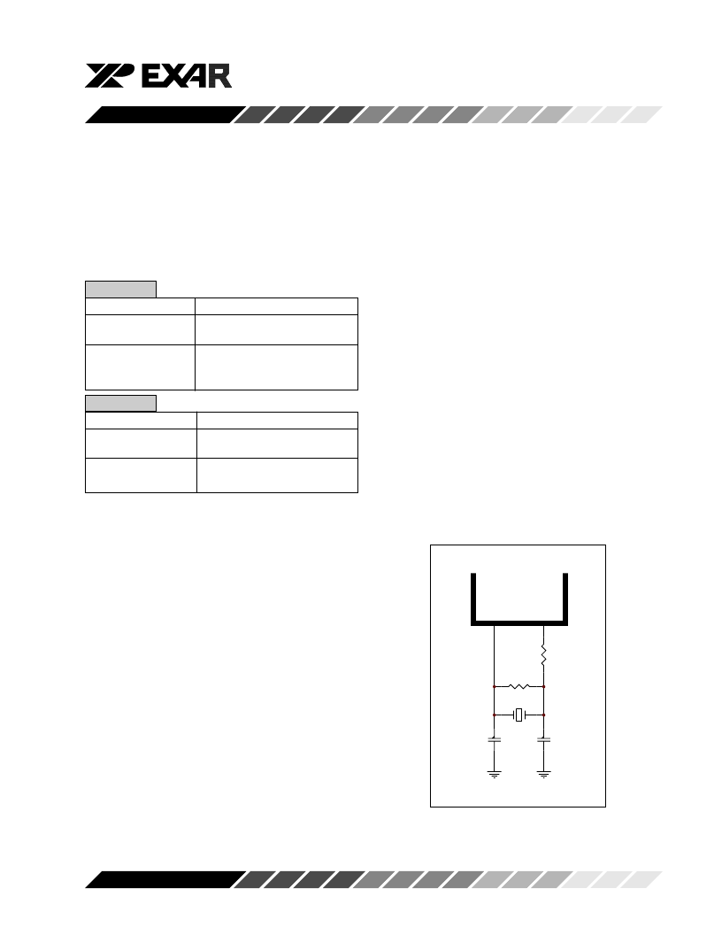
Figure 3, TYPICAL EXTERNAL CRYSTAL OSCILLA-
TOR CONNECTION
C1
22-47pF
C2
22-47pF
Y1
1.8432 - 24 MHz
R1
0-120
(Optional)
R2
1M
XTAL1
XTAL2
相關(guān)PDF資料 |
PDF描述 |
|---|---|
| ST16C552 | Dual UART with 16-Byte FIFO and Parallel Printer Port(雙通用異步接收器/發(fā)送器(帶16字節(jié)的先進先出和并行打印機端口)) |
| ST16C552A | Dual UART with 16-Byte FIFO and Parallel Printer Port(雙通用異步接收器/發(fā)送器(帶16字節(jié)的先進先出和并行打印機端口)) |
| ST16C554DCJ68 | QUAD UART WITH 16-BYTE FIFOS |
| ST68C554 | QUAD UART WITH 16-BYTE FIFOS |
| ST16C554DIJ68 | Plug-In Relay; Contacts:DPDT; Contact Carry Current:15A; Coil Voltage AC Max:120V; Relay Mounting:Plug-In; Relay Terminals:Quick Connect; Coil Resistance:4430ohm RoHS Compliant: Yes |
相關(guān)代理商/技術(shù)參數(shù) |
參數(shù)描述 |
|---|---|
| ST16C550_05 | 制造商:EXAR 制造商全稱:EXAR 功能描述:UART WITH 16-BYTE FIFO’s |
| ST16C550CJ44 | 制造商:Exar 功能描述:Bulk |
| ST16C550CJ44-F | 功能描述:UART 接口集成電路 2.97V-5.5V 16B FIFO temp 0C to 70C; UART RoHS:否 制造商:Texas Instruments 通道數(shù)量:2 數(shù)據(jù)速率:3 Mbps 電源電壓-最大:3.6 V 電源電壓-最小:2.7 V 電源電流:20 mA 最大工作溫度:+ 85 C 最小工作溫度:- 40 C 封裝 / 箱體:LQFP-48 封裝:Reel |
| ST16C550CJ44TR-F | 功能描述:UART 接口集成電路 SNGL UART W/16BYTE FIFO RoHS:否 制造商:Texas Instruments 通道數(shù)量:2 數(shù)據(jù)速率:3 Mbps 電源電壓-最大:3.6 V 電源電壓-最小:2.7 V 電源電流:20 mA 最大工作溫度:+ 85 C 最小工作溫度:- 40 C 封裝 / 箱體:LQFP-48 封裝:Reel |
| ST16C550CP40 | 功能描述:UART 接口集成電路 SINGLE UART W/16 BYTE FIFO RoHS:否 制造商:Texas Instruments 通道數(shù)量:2 數(shù)據(jù)速率:3 Mbps 電源電壓-最大:3.6 V 電源電壓-最小:2.7 V 電源電流:20 mA 最大工作溫度:+ 85 C 最小工作溫度:- 40 C 封裝 / 箱體:LQFP-48 封裝:Reel |
發(fā)布緊急采購,3分鐘左右您將得到回復。