- 您現(xiàn)在的位置:買賣IC網(wǎng) > PDF目錄299927 > SST49LF008C-33-4C-NHE 1M X 8 FLASH 3V PROM, 11 ns, PQCC32 PDF資料下載
參數(shù)資料
| 型號: | SST49LF008C-33-4C-NHE |
| 元件分類: | PROM |
| 英文描述: | 1M X 8 FLASH 3V PROM, 11 ns, PQCC32 |
| 封裝: | ROHS COMPLIANT, PLASTIC, MS-016AE, LCC-32 |
| 文件頁數(shù): | 18/36頁 |
| 文件大小: | 509K |
| 代理商: | SST49LF008C-33-4C-NHE |
第1頁第2頁第3頁第4頁第5頁第6頁第7頁第8頁第9頁第10頁第11頁第12頁第13頁第14頁第15頁第16頁第17頁當前第18頁第19頁第20頁第21頁第22頁第23頁第24頁第25頁第26頁第27頁第28頁第29頁第30頁第31頁第32頁第33頁第34頁第35頁第36頁
Advance Information
4 Mbit / 8 Mbit LPC Serial Flash
SST49LF004C / SST49LF008C
25
200 Silicon Storage Technology, Inc.
S71292-00-000
1/06
AUTO-ADDRESS INCREMENT (AAI) MODE
AAI Mode with Multi-byte Programming
AAI mode with multi-byte programming is provided for high-
speed production programming. Auto-Address Increment
mode requires only one address load for each 128-byte
page of data. The Multi-Byte Programming feature allows
simultaneous multi-byte programming. Note: The Security
ID area and the Protected Data Area cannot be pro-
grammed using AAI mode.
Taking the WP#/AAI pin to the Supervoltage VH enables
the AAI mode. The AAI command is started as a normal
Firmware Memory cycle. LD# should be low (VIL) as long
as data is being loaded into the device. In the MADDR field,
the host may input any address within the 128-byte page to
be programmed. The least significant seven bits of the
address field will be ignored and the device will begin pro-
gramming at the beginning of the 128-byte page (i.e., the
address will be page-aligned). The device Ready/Busy sta-
tus is output on the RY/BY# pin.
Data is accepted until the internal buffer is full. At that point
RY/BY# goes low (busy) to indicate that the internal buffer
is full and cannot accept any more data. When the device
is ready, RY/BY# pin goes high and indicates to the host
that more data (the next group of bytes) can be accepted
LD# is taken high by the host after loading the final byte(s)
of the 128-byte page. the RY/BY# signal remains low until
the completion of internal programming. After the comple-
tion of programming, the part will go into idle mode and the
RY/BY# will go high indicating that the AAI command has
been completed (see Table 19). A subsequent AAI com-
mand may be initiated to begin programming the next 128-
byte page.
Data will be accepted by the device as long as LD# is low
and RY/BY# is high (until the last byte of the 128-byte page
has been entered). For partial data-loads (i.e., less than
128 Bytes), LD# may be taken high (VIH) to end the data
loading. If LD# goes high before the full 128-byte page has
been entered, the device will program the data which has
been entered to that point, and then terminate the AAI
page programming command. Any incompletely loaded
data byte (nibble) will not be programmed. The device will
signify completion of the command by driving RY/BY# high.
Once RY/BY# goes high, LD# can be taken low to begin a
new AAI programming operation at a different address
location.
The RY/BY# pin will stay low while internal programming
completes. When the entire 128-byte page has been pro-
grammed, the device will return to the idle mode and the
RY/BY# pin will go high (VIH) to indicate the AAI command
has been completed.
The user may terminate AAI programming by dropping the
WP#/AAI pin to TTL levels (VIH/VIL) as long as LD# is high
and RY/BY# returns to high indicating the completion of the
AAI cycle. Software block-locking will be disabled in AAI
mode (all blocks will be write-unlocked). If AAI drops below
the Supervoltage VH before RY/BY# returns to high (and
LD# high), the contents of the page may be indeterminate.
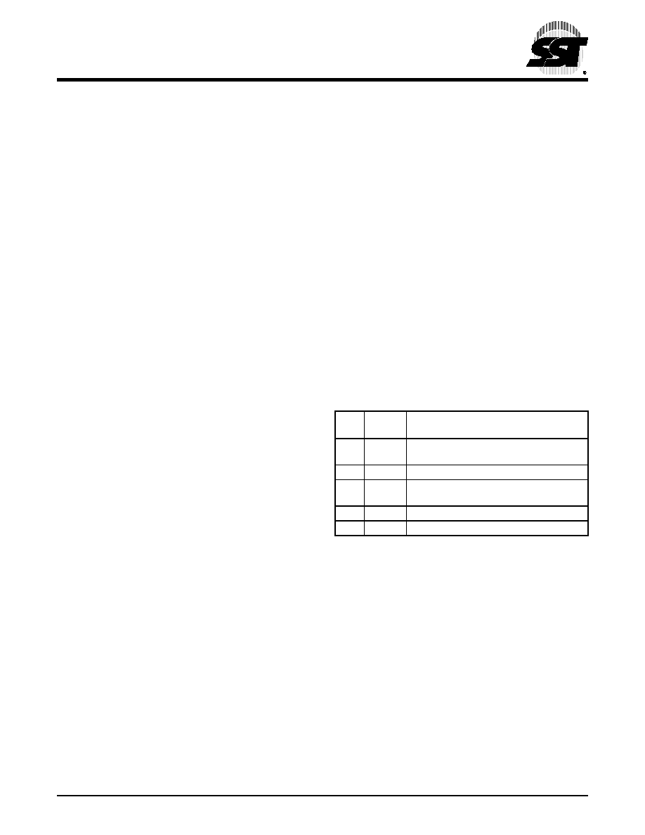
TABLE 19: LD# INPUT AND RY/BY# STATUS IN
AAI MODE
LD#
state
RY/BY#
status
RY/BY#
Flag indication
L
H
Device is Ready, can accept more data
until the last (128th) byte.
L
Device is Busy, cannot accept more data
L
H
Device is Ready for next operation if
previous data is the last (128th) byte.
H
Device is Ready for next operation
H
L
Device is Busy programming
T19.0 1292
相關PDF資料 |
PDF描述 |
|---|---|
| SSU-131MAT | SLIDE SWITCH, SP3T, LATCHED, 0.3A, 4VDC, SURFACE MOUNT-RIGHT ANGLE |
| SSU-121ART | SLIDE SWITCH, SPDT, LATCHED, 0.3A, 4VDC, SURFACE MOUNT-RIGHT ANGLE |
| SSW-102-22-F-D-VS | 4 CONTACT(S), FEMALE, STRAIGHT TWO PART BOARD CONNECTOR, SURFACE MOUNT, SOCKET |
| SSW-102-22-F-S-VS | 2 CONTACT(S), FEMALE, STRAIGHT TWO PART BOARD CONNECTOR, SURFACE MOUNT, SOCKET |
| SSW-102-22-G-D-VS | 4 CONTACT(S), FEMALE, STRAIGHT TWO PART BOARD CONNECTOR, SURFACE MOUNT, SOCKET |
相關代理商/技術參數(shù) |
參數(shù)描述 |
|---|---|
| SST49LF008C-33-4C-WHE | 制造商:SST 制造商全稱:Silicon Storage Technology, Inc 功能描述:4 Mbit / 8 Mbit LPC Serial Flash |
| SST49LF016C | 制造商:SST 制造商全稱:Silicon Storage Technology, Inc 功能描述:16 Mbit LPC Serial Flash |
| SST49LF016C-33-4C-EIE | 功能描述:閃存 16M (2Mx8) 33MHz 3.0-3.6V Commercial RoHS:否 制造商:ON Semiconductor 數(shù)據(jù)總線寬度:1 bit 存儲類型:Flash 存儲容量:2 MB 結構:256 K x 8 定時類型: 接口類型:SPI 訪問時間: 電源電壓-最大:3.6 V 電源電壓-最小:2.3 V 最大工作電流:15 mA 工作溫度:- 40 C to + 85 C 安裝風格:SMD/SMT 封裝 / 箱體: 封裝:Reel |
| SST49LF016C-33-4C-EIE-T | 功能描述:閃存 3.0 to 3.6V 16Mbit LPC Firmware 閃存 RoHS:否 制造商:ON Semiconductor 數(shù)據(jù)總線寬度:1 bit 存儲類型:Flash 存儲容量:2 MB 結構:256 K x 8 定時類型: 接口類型:SPI 訪問時間: 電源電壓-最大:3.6 V 電源電壓-最小:2.3 V 最大工作電流:15 mA 工作溫度:- 40 C to + 85 C 安裝風格:SMD/SMT 封裝 / 箱體: 封裝:Reel |
| SST49LF016C-33-4C-NHE | 功能描述:閃存 16M (2Mx8) 33MHz 3.0-3.6V Commercial RoHS:否 制造商:ON Semiconductor 數(shù)據(jù)總線寬度:1 bit 存儲類型:Flash 存儲容量:2 MB 結構:256 K x 8 定時類型: 接口類型:SPI 訪問時間: 電源電壓-最大:3.6 V 電源電壓-最小:2.3 V 最大工作電流:15 mA 工作溫度:- 40 C to + 85 C 安裝風格:SMD/SMT 封裝 / 箱體: 封裝:Reel |
發(fā)布緊急采購,3分鐘左右您將得到回復。