- 您現(xiàn)在的位置:買賣IC網(wǎng) > PDF目錄374697 > SAF82526 (INFINEON TECHNOLOGIES AG) Data Communications ICs PDF資料下載
參數(shù)資料
| 型號: | SAF82526 |
| 廠商: | INFINEON TECHNOLOGIES AG |
| 英文描述: | Data Communications ICs |
| 中文描述: | 數(shù)據(jù)通信集成電路 |
| 文件頁數(shù): | 13/126頁 |
| 文件大?。?/td> | 730K |
| 代理商: | SAF82526 |
第1頁第2頁第3頁第4頁第5頁第6頁第7頁第8頁第9頁第10頁第11頁第12頁當前第13頁第14頁第15頁第16頁第17頁第18頁第19頁第20頁第21頁第22頁第23頁第24頁第25頁第26頁第27頁第28頁第29頁第30頁第31頁第32頁第33頁第34頁第35頁第36頁第37頁第38頁第39頁第40頁第41頁第42頁第43頁第44頁第45頁第46頁第47頁第48頁第49頁第50頁第51頁第52頁第53頁第54頁第55頁第56頁第57頁第58頁第59頁第60頁第61頁第62頁第63頁第64頁第65頁第66頁第67頁第68頁第69頁第70頁第71頁第72頁第73頁第74頁第75頁第76頁第77頁第78頁第79頁第80頁第81頁第82頁第83頁第84頁第85頁第86頁第87頁第88頁第89頁第90頁第91頁第92頁第93頁第94頁第95頁第96頁第97頁第98頁第99頁第100頁第101頁第102頁第103頁第104頁第105頁第106頁第107頁第108頁第109頁第110頁第111頁第112頁第113頁第114頁第115頁第116頁第117頁第118頁第119頁第120頁第121頁第122頁第123頁第124頁第125頁第126頁
Semiconductor Group
13
82525
82526
82525
82526
SAB
SAB
SAF
SAF
INT
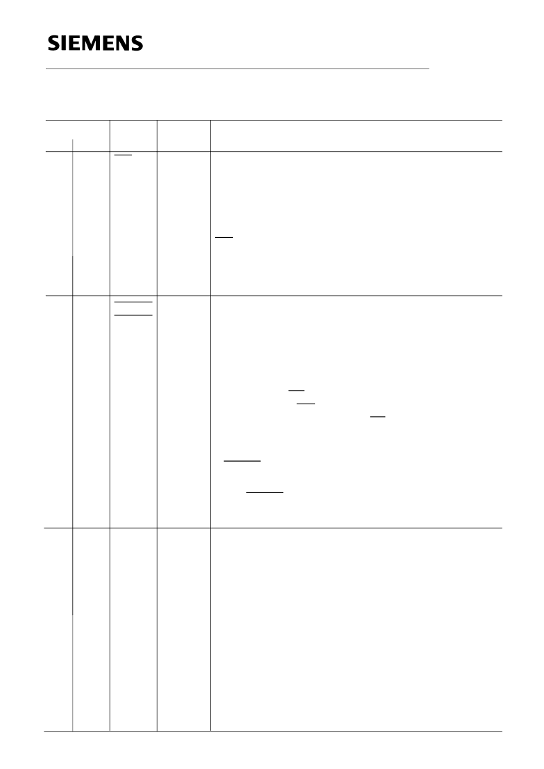
Pin Definitions and Functions
(cont’d)
Pin No.
Symbol
Input (I)
Output (O)
Function
30
29
I
34
31
AxCLK
A
AxCLK
B
I
DMA Acknowledge
(channel A/channel B)
When low, this input signal from the DMA controller notifies,
the HSCX, that the requested DMA cycle controlled via
DRQxx (pins 37–40) is in progress, i.e. the DMA controller
has achieved bus mastership from the CPU and will start
data transfer cycles (either read or write).
Together with RD, if DMA has been requested from the
receiver, or with WR, if DMA has been requested from the
transmitter, this input works like CS to enable a data byte to
be read from or written to the top of the receive or transmit
FIFO of the specified channel.
If DACKn is active, the input on pins A0–A6 is ignored and
the FIFOs are implicitly selected.
If the DACKn signals are not used, these pins must be
connected to
V
DD
.
Alternative Clock
(channel A/channel B)
These pins realize several input functions. Depending on
the selected clock mode, they may supply either a
CD (= Carrier Detect) modem control or general purpose
input.
This pin can be programmed to functions as receiver
enable if the "auto start" feature is selected (CAS bit in
XBCH set). The state at this pin can be read from VSTR
register,
or a receive strobe signal (clock mode 1)
–
or a frame synchronization signal in time-slot oriented
operation mode (clock mode 5)
or, together with RxCLK, a crystal connection for the
internal oscillator (clock mode 4, 6, 7, AxCLK A only).
–
–
–
DACKA
DACKB
28
oD
Interrupt Request
The signal is activated, when the HSCX requests an
interrupt.
The CPU may determine the particular source and cause of
the interrupt by reading the HSCX’s interrupt status
registers. (ISTA, EXIR).
INT is an open drain output, thus the interrupt requests
outputs of several HSCX’s can be connected to one
interrupt input in a "wired-or" combination.
This pin must be connected to a pull-up resistor.
P-LCC P-MQFP
35
34
39
36
33
相關PDF資料 |
PDF描述 |
|---|---|
| SAF82526N | Data Communications ICs |
| SAB82525 | Data Communications ICs |
| SAB82525H | Data Communications ICs |
| SAF82532H-10 | ICs for Communications |
| SAB82532 | ICs for Communications |
相關代理商/技術參數(shù) |
參數(shù)描述 |
|---|---|
| SAF82526HV2.1-HSCX-1 | 制造商:Rochester Electronics LLC 功能描述:- Bulk |
| SAF82526N | 制造商:INFINEON 制造商全稱:Infineon Technologies AG 功能描述:Data Communications ICs |
| SAF82526NV2.2 | 功能描述:網(wǎng)絡控制器與處理器 IC T/E RoHS:否 制造商:Micrel 產(chǎn)品:Controller Area Network (CAN) 收發(fā)器數(shù)量: 數(shù)據(jù)速率: 電源電流(最大值):595 mA 最大工作溫度:+ 85 C 安裝風格:SMD/SMT 封裝 / 箱體:PBGA-400 封裝:Tray |
| SAF82526NV2.2XT | 制造商:Infineon Technologies AG 功能描述:Communication Controller 44-Pin PLCC T/R |
| SAF82532 | 制造商:INFINEON 制造商全稱:Infineon Technologies AG 功能描述:ICs for Communications |
發(fā)布緊急采購,3分鐘左右您將得到回復。