- 您現(xiàn)在的位置:買賣IC網(wǎng) > PDF目錄372063 > RH80530GZ009512 Microprocessor PDF資料下載
參數(shù)資料
| 型號(hào): | RH80530GZ009512 |
| 元件分類: | 微處理器 |
| 英文描述: | Microprocessor |
| 中文描述: | 微處理器 |
| 文件頁(yè)數(shù): | 14/89頁(yè) |
| 文件大小: | 1672K |
| 代理商: | RH80530GZ009512 |
第1頁(yè)第2頁(yè)第3頁(yè)第4頁(yè)第5頁(yè)第6頁(yè)第7頁(yè)第8頁(yè)第9頁(yè)第10頁(yè)第11頁(yè)第12頁(yè)第13頁(yè)當(dāng)前第14頁(yè)第15頁(yè)第16頁(yè)第17頁(yè)第18頁(yè)第19頁(yè)第20頁(yè)第21頁(yè)第22頁(yè)第23頁(yè)第24頁(yè)第25頁(yè)第26頁(yè)第27頁(yè)第28頁(yè)第29頁(yè)第30頁(yè)第31頁(yè)第32頁(yè)第33頁(yè)第34頁(yè)第35頁(yè)第36頁(yè)第37頁(yè)第38頁(yè)第39頁(yè)第40頁(yè)第41頁(yè)第42頁(yè)第43頁(yè)第44頁(yè)第45頁(yè)第46頁(yè)第47頁(yè)第48頁(yè)第49頁(yè)第50頁(yè)第51頁(yè)第52頁(yè)第53頁(yè)第54頁(yè)第55頁(yè)第56頁(yè)第57頁(yè)第58頁(yè)第59頁(yè)第60頁(yè)第61頁(yè)第62頁(yè)第63頁(yè)第64頁(yè)第65頁(yè)第66頁(yè)第67頁(yè)第68頁(yè)第69頁(yè)第70頁(yè)第71頁(yè)第72頁(yè)第73頁(yè)第74頁(yè)第75頁(yè)第76頁(yè)第77頁(yè)第78頁(yè)第79頁(yè)第80頁(yè)第81頁(yè)第82頁(yè)第83頁(yè)第84頁(yè)第85頁(yè)第86頁(yè)第87頁(yè)第88頁(yè)第89頁(yè)
Mobile Intel
Pentium
III Processor-M Datasheet
14
Datasheet
298340-002
2.1.6
Signal Differences Between the Mobile Pentium III Processor
(in BGA2 and Micro-PGA2 Packages) and the Mobile Intel
Pentium III Processor-M
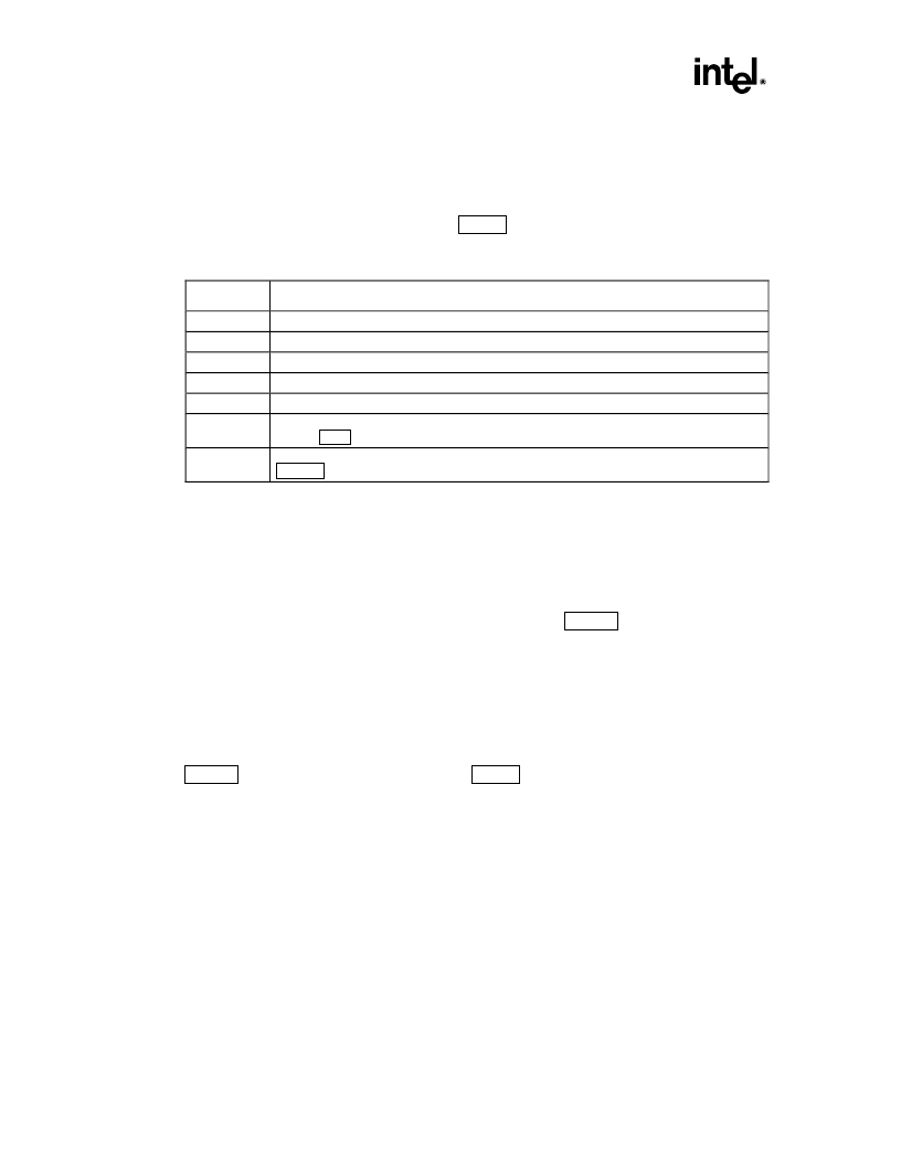
A list of new and changed signals is shown in Table 1.
Table 1. New and Revised Mobile Intel Pentium III Processor-M Signals
Signals
Function
BCLK, BCLK# Differential host clk signals.
CLKREF
Host Clock reference signal in Single Ended Clocking mode.
BSEL[1:0]
Signals are output only instead of I/O. Please refer to the Appendix for details.
DPSLP#
Deep Sleep pin (replaces SLP# pin on the Pentium III processor).
NCTRL
AGTL output buffer pull down impedance control.
VID[4:0]
Voltage Identification (different implementation from Pentium III processor). Please refer to
Section 3.2.3 for details.
VTTPWRGD
Power Good signal for VCCT, which indicates that, the VID signals are stable. Please refer to
Figure 3 for VTTPWRGD system level connections.
2.2
Power Management
2.2.1
Clock Control Architecture
The Mobile Pentium
III
Processor-M clock control architecture (Figure 1) has been optimized for
leading edge mobile computer designs. The clock control architecture consists of six different clock
states: Normal, Auto Halt, Quick Start, HALT/Grant Snoop, Deep Sleep and Deeper Sleep states. The
Auto Halt state provides a low-power clock state that can be controlled through the software execution
of the HLT instruction. The Quick Start state provides a very low power and low exit latency clock
state that can be used for hardware controlled “idle” computer states. The Deep Sleep and Deeper
Sleep states provide extremely low-power states that can be used for “Power-On-Suspend” computer
states, which is an alternative to shutting off the processor’s power. The exit latency of the Deep Sleep
state is 30
μ
sec in the Mobile Pentium
III
Processor-M. Performing state transitions not shown in
Figure 1 is neither recommended nor supported. Table 2 provides the clock state characteristics, which
are described in detail in the following sections.
2.2.2
Normal State
The Normal state of the processor is the normal operating mode where the processor’s core clock is
running and the processor is actively executing instructions.
2.2.3
Auto Halt State
This is a low-power mode entered by the processor through the execution of the HLT instruction. A
transition to the Normal state is made by a halt break event (one of the following signals going active:
NMI, INTR, BINIT#, INIT#, RESET#, FLUSH#, or SMI#).
相關(guān)PDF資料 |
PDF描述 |
|---|---|
| RH80530NZ001256 | Microprocessor |
| RH80530NZ004256 | MICROPROCESSOR|32-BIT|CMOS|PGA|478PIN|CERAMIC |
| RH80530NZ006256 | MICROPROCESSOR|32-BIT|CMOS|PGA|478PIN|CERAMIC |
| RH80530NZ009256 | MICROPROCESSOR|32-BIT|CMOS|PGA|478PIN|CERAMIC |
| RH80530WZ014256 | Microprocessor |
相關(guān)代理商/技術(shù)參數(shù) |
參數(shù)描述 |
|---|---|
| RH80530GZ866512 | 制造商:Rochester Electronics LLC 功能描述:MOBILE P3 PROCESSOR; 866 MHZ; 512K OD; 1.4V; BGA2 - Bulk |
| RH80530MZ733256 | 制造商:Rochester Electronics LLC 功能描述:- Bulk |
| RH80530NZ001256 | 制造商:Rochester Electronics LLC 功能描述:- Bulk |
| RH80530NZ001256S L6AB | 制造商:Intel 功能描述:MPU Celeron? Processor 64-Bit 0.13um 1GHz 478-Pin uFCPGA |
| RH80530NZ004256 | 制造商:未知廠家 制造商全稱:未知廠家 功能描述:MICROPROCESSOR|32-BIT|CMOS|PGA|478PIN|CERAMIC |
發(fā)布緊急采購(gòu),3分鐘左右您將得到回復(fù)。