- 您現(xiàn)在的位置:買賣IC網(wǎng) > PDF目錄296800 > PF38F3050L0YUQ3A (INTEL CORP) SPECIALTY MEMORY CIRCUIT, PBGA88 PDF資料下載
參數(shù)資料
| 型號(hào): | PF38F3050L0YUQ3A |
| 廠商: | INTEL CORP |
| 元件分類: | 存儲(chǔ)器 |
| 英文描述: | SPECIALTY MEMORY CIRCUIT, PBGA88 |
| 封裝: | 8 X 10 MM, 1.20 MM HEIGHT, ROHS COMPLIANT, SCSP-88 |
| 文件頁(yè)數(shù): | 52/70頁(yè) |
| 文件大?。?/td> | 1193K |
| 代理商: | PF38F3050L0YUQ3A |
第1頁(yè)第2頁(yè)第3頁(yè)第4頁(yè)第5頁(yè)第6頁(yè)第7頁(yè)第8頁(yè)第9頁(yè)第10頁(yè)第11頁(yè)第12頁(yè)第13頁(yè)第14頁(yè)第15頁(yè)第16頁(yè)第17頁(yè)第18頁(yè)第19頁(yè)第20頁(yè)第21頁(yè)第22頁(yè)第23頁(yè)第24頁(yè)第25頁(yè)第26頁(yè)第27頁(yè)第28頁(yè)第29頁(yè)第30頁(yè)第31頁(yè)第32頁(yè)第33頁(yè)第34頁(yè)第35頁(yè)第36頁(yè)第37頁(yè)第38頁(yè)第39頁(yè)第40頁(yè)第41頁(yè)第42頁(yè)第43頁(yè)第44頁(yè)第45頁(yè)第46頁(yè)第47頁(yè)第48頁(yè)第49頁(yè)第50頁(yè)第51頁(yè)當(dāng)前第52頁(yè)第53頁(yè)第54頁(yè)第55頁(yè)第56頁(yè)第57頁(yè)第58頁(yè)第59頁(yè)第60頁(yè)第61頁(yè)第62頁(yè)第63頁(yè)第64頁(yè)第65頁(yè)第66頁(yè)第67頁(yè)第68頁(yè)第69頁(yè)第70頁(yè)
768-Mbit LQ Family with Synchronous PSRAM
Intel StrataFlash Wireless Memory (L18 SCSP)
Datasheet
August 2006
56
Order Number: 314476-001
768-Mbit LQ Family with Synchronous PSRAM
12.2.1.1
PSRAM BCR Operating Mode
The PSRAM supports three different interface access protocols:
SRAM-type protocol with asynchronous read and write accesses
NOR-Flash-type protocol with synchronous read and asynchronous write accesses
FULL SYNCHRONOUS mode with synchronous read and synchronous write accesses
Operating the PSRAM in synchronous mode maximizes bandwidth. The NOR-Flash type
mode is the recommended mode for legacy systems which are not able to run the
synchronous write protocol. The Operating Mode bit BCR15 defines whether the device
is operating in synchronous (fully or partially) mode or asynchronous mode.
When BCR15 is set low, the mode of write operation, NOR-flash or Full synchronous, is
adaptively detected by detecting a rising clock edge during ADV# valid. If a rising clock
edge occurs within ADV# valid, Full synchronous write is detected. If there is no rising
clock edge then NOR-Flash write is detected and CE# must go high when transitioning
from asynchronous to synchronous operation or when transitioning from synchronous
to asynchronous operation..
When BCR15 is set high, the SRAM-type mode of operation is selected.
Warning:
When operating the PSRAM as an ADMux I/O interface by connecting the lower sixteen
(16) addresses, A[15:0], to the data pins, ADV# must be de-asserted during any data
phase cycle.
12.2.1.2
PSRAM Initial Latency BCR Bit
The PSRAM latency is related to the number of clock cycles from the burst-init
command to be either 1st valid data output (read burst) or 1st valid data input (burst
write.) In Fixed Latency mode, the number of clock cycles from bust-init command to
valid data is always fixed as defined by the Latency Counter setting in the BCR. In
Variable Latency mode, the number of clock cycles from bust-init command to valid
data output (read burst) is variable depending on internal device operation. The
minimum latency in Variable Latency mode is defined by the Latency Counter setting in
the BCR. Additional WAIT cycles may be added in Variable Latency mode if the burst-
init Read command collides with an on-going internal refresh. Additional WAIT cycles
are not added for burst-init Write commands in Variable Latency mode.
12.2.1.3
PSRAM Latency Counter BCR Bit
The latency counter defines the number of clock cycles that pass before the first output
data is valid (read burst) or before the first input data is valid (read burst.) Each
Latency Code setting has an associate maximum PSRAM clock frequency. In the case of
Variable Latency the first access delay might be extended by additional wait cycles in
case the burst read access collides with an ongoing self-refresh operation. The allowed
values of the Latency Counter also depend on the Initial Latency setting in BCR.
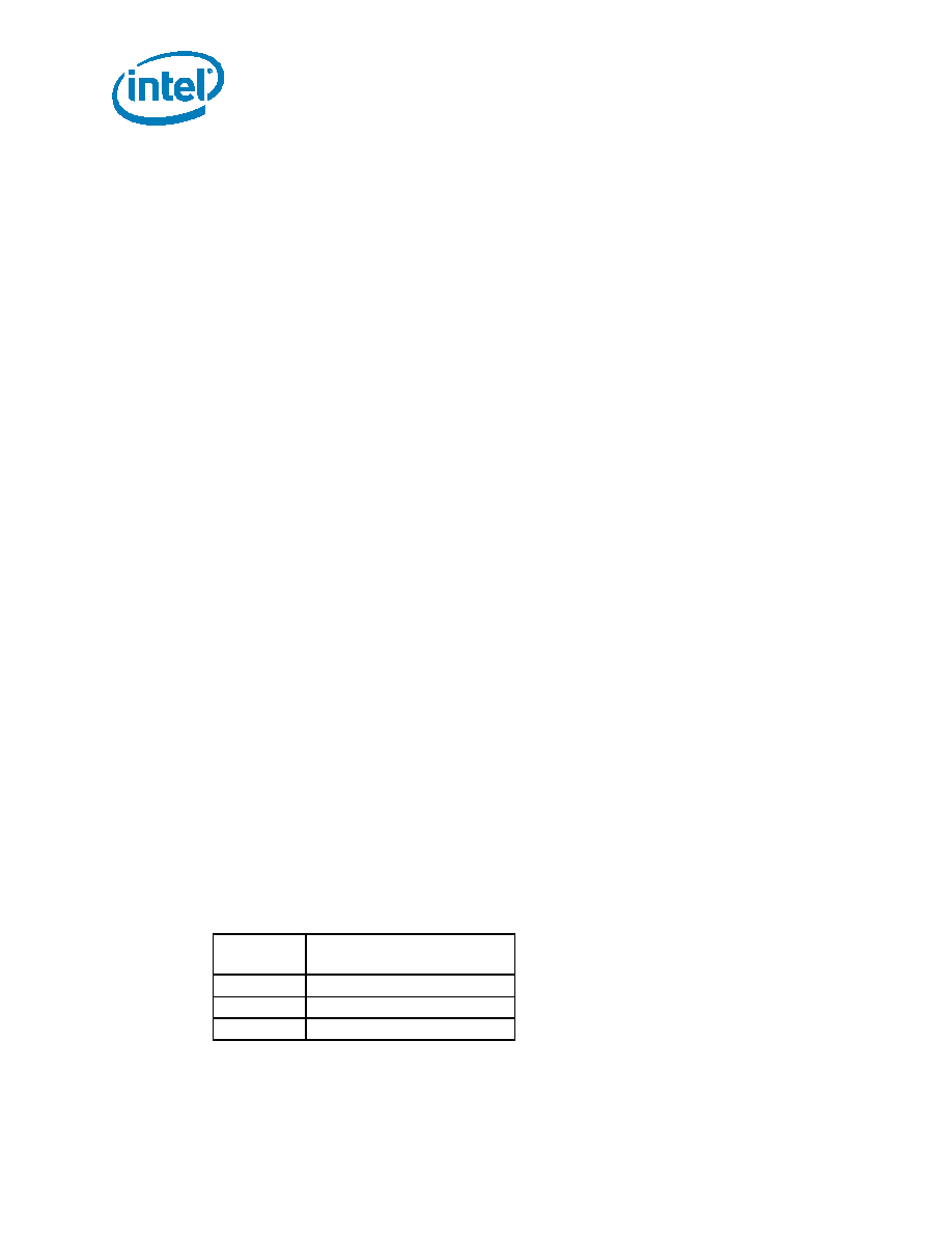
Table 20. Optional PSRAM BCR Latency Counter Settings in Variable Latency
Latency
Counter
PSRAM
010
Code 2; Max 54 MHz
011
Code 3; Max 80 MHz
Others
Reserved
相關(guān)PDF資料 |
PDF描述 |
|---|---|
| PFC04108.2UHKT | 1 ELEMENT, 8.2 uH, GENERAL PURPOSE INDUCTOR |
| PFC04101.8UHKT | 1 ELEMENT, 1.8 uH, GENERAL PURPOSE INDUCTOR |
| PFC041022UHKB | 1 ELEMENT, 22 uH, GENERAL PURPOSE INDUCTOR |
| PFC04102700UHKT | 1 ELEMENT, 2700 uH, GENERAL PURPOSE INDUCTOR |
| PFC0410270UHKB | 1 ELEMENT, 270 uH, GENERAL PURPOSE INDUCTOR |
相關(guān)代理商/技術(shù)參數(shù) |
參數(shù)描述 |
|---|---|
| PF38F3050M0Y0CE0 | 制造商:Micron Technology Inc 功能描述:WIRELESS - Trays |
| PF38F3050M0Y0CE3 | 制造商:Micron Technology Inc 功能描述:WIRELESS - Trays |
| PF38F3050M0Y0CEA | 制造商:Micron Technology Inc 功能描述:128BA/64PS SCSP 1.8 X16C HF - Trays 制造商:Micron Technology Inc 功能描述:IC FLASH 192M |
| PF38F3050M0Y0CEB | 制造商:Micron Technology Inc 功能描述:8MX16/4MX16 MCP PLASTIC PBF TFBGA 1.8V COMBO - Tape and Reel |
| PF38F3050M0Y0CEB TR | 制造商:Micron Technology Inc 功能描述:IC FLASH 192M |
發(fā)布緊急采購(gòu),3分鐘左右您將得到回復(fù)。