- 您現(xiàn)在的位置:買賣IC網(wǎng) > PDF目錄359234 > MT90401AB1 (ZARLINK SEMICONDUCTOR INC) SONET/SDH System Synchronizer PDF資料下載
參數(shù)資料
| 型號(hào): | MT90401AB1 |
| 廠商: | ZARLINK SEMICONDUCTOR INC |
| 元件分類: | 數(shù)字傳輸電路 |
| 英文描述: | SONET/SDH System Synchronizer |
| 中文描述: | ATM/SONET/SDH SUPPORT CIRCUIT, PQFP80 |
| 封裝: | 14 X 14 MM, 1.40 MM HEIGHT, LEAD FREE, MS-026BEC, LQFP-80 |
| 文件頁數(shù): | 5/38頁 |
| 文件大?。?/td> | 650K |
| 代理商: | MT90401AB1 |
第1頁第2頁第3頁第4頁當(dāng)前第5頁第6頁第7頁第8頁第9頁第10頁第11頁第12頁第13頁第14頁第15頁第16頁第17頁第18頁第19頁第20頁第21頁第22頁第23頁第24頁第25頁第26頁第27頁第28頁第29頁第30頁第31頁第32頁第33頁第34頁第35頁第36頁第37頁第38頁
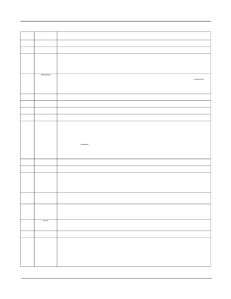
MT90401
Data Sheet
5
Zarlink Semiconductor Inc.
45
V
SS5
C19o
Digital ground.
0 Volts
46
Clock 19.44 MHz (CMOS Output).
This output is used in OC-N and STM-N applications.
47
RSEL
Reference Source Select (Input).
A logic low selects the PRI (primary) reference source
as the input reference signal and a logic high selects the SEC (secondary) input. The logic
level at this input is gated in by the rising edge of F8o. For more details see RSEL bit
description in Table 6 - Control Register 1 (Address 00H - Read/Write).
48
TCLR
TIE Circuit Clear (Input).
A logic low at this input clears the Time Interval Error (TIE)
correction circuit resulting in a realignment of output phase with input phase. The TCLR pin
should be held low for a minimum of 300 ns. When this pin is held low, the time interval error
correction circuit is disabled.
49
V
DD3
NC
Positive Power Supply. Digital supply
.
50
No Connection.
51
C20i
20 MHz Clock Input (5 V tolerant Input).
This pin is the input for the master 20 MHz clock.
52
V
SS7
C34/C44
Digital ground.
0Volts
53
Controlled Clock 34.368 MHz / Clock 44.736 MHz (CMOS Output).
This output clock is
programmable to be either 34.368 MHz (for E3 applications) or 44.736 MHz (for DS3
applications). The output clock is controlled via control pins in Hardware Mode or control
bits when the device is in Microport Mode.
If the E3DS3/OC3 control pin or control bit is high, the C34/C44 pin will output its nominal
frequency. If the E3DS3/OC3 control pin or bit is low, the C34/C44 pin will output its nominal
frequency divided by 4. (C8.5o/C11o)
54
V
DD4
Positive Power Supply.
Digital supply.
55
HOLDOVER
Holdover (CMOS Output).
This output goes high when the device is in holdover mode.
56
PCCi
Phase Continuity Control Input (3 V Input).
The signal at this pin affects the state
changes between Primary Holdover Mode and Primary Normal Mode and Primary Holdover
Mode and Secondary Normal Mode. The logic level at this input is gated by the rising edge
of F8o. See Figure 12, “Control State Diagram” on page 21 for details.
57
LOCK
Lock Indicator (CMOS Output).
This output goes high when the PLL is in frequency lock
to the input reference.
58
FLOCK
Fast Lock Mode (Input).
In hardware mode, hold this pin high to lock faster than normal to
the input reference. This pin performs no function if the device is not in hardware mode. In
Fast Lock Mode, the wander generation of the PLL is, of necessity, compromised.
59
DS
Data Strobe (5 V tolerant Input)
. This input is the active low data strobe of the Motorola
processor interface.
60
IC
Internal Connection.
Tie low for normal operation.
61
SECOOR
Secondary Reference Out Of Capture Range (CMOS Output).
A logic high at this pin
indicates that the secondary reference is off the PLL center frequency by more than 12
ppm. The measurement is done on a 1 second basis using a signal derived from the
20 MHz clock input on the C20i pin. When the accuracy of the 20 MHz clock is
±
4.6 ppm
the effective out of range limits of the SECOOR signal will be
+
16.6 ppm to -7.4 ppm or
+7.4 ppm to -16.6 ppm.
Pin Description (continued)
Pin #
Name
Description
相關(guān)PDF資料 |
PDF描述 |
|---|---|
| MT9040 | T1/E1 Synchronizer |
| MT9040AN | T1/E1 Synchronizer |
| MT9043 | T1/E1 System Synchronizer |
| MT9043AN | T1/E1 System Synchronizer |
| MT9043AN48PINSSOP | T1/E1 System Synchronizer |
相關(guān)代理商/技術(shù)參數(shù) |
參數(shù)描述 |
|---|---|
| MT9040AN | 制造商:ZARLINK 制造商全稱:Zarlink Semiconductor Inc 功能描述:T1/E1 Synchronizer |
| MT9040AN1 | 制造商:Microsemi Corporation 功能描述:FRAMER E1 /T1 3.3V 48SSOP - Rail/Tube |
| MT9040ANR1 | 制造商:Microsemi Corporation 功能描述:FRAMER E1 /T1 3.3V 48SSOP - Tape and Reel |
| MT9041 | 制造商:MITEL 制造商全稱:Mitel Networks Corporation 功能描述:Multiple Output Trunk PLL |
| MT9041AP | 制造商:Microsemi Corporation 功能描述:WAN/PLL 制造商:Zarlink Semiconductor Inc 功能描述:WAN/PLL |
發(fā)布緊急采購,3分鐘左右您將得到回復(fù)。