- 您現(xiàn)在的位置:買賣IC網(wǎng) > PDF目錄296559 > MIC2591B-5YTQ (MICREL INC) 1-CHANNEL POWER SUPPLY SUPPORT CKT, PQFP48 PDF資料下載
參數(shù)資料
| 型號: | MIC2591B-5YTQ |
| 廠商: | MICREL INC |
| 元件分類: | 電源管理 |
| 英文描述: | 1-CHANNEL POWER SUPPLY SUPPORT CKT, PQFP48 |
| 封裝: | LEAD FREE, TQFP-48 |
| 文件頁數(shù): | 21/34頁 |
| 文件大小: | 1920K |
| 代理商: | MIC2591B-5YTQ |
第1頁第2頁第3頁第4頁第5頁第6頁第7頁第8頁第9頁第10頁第11頁第12頁第13頁第14頁第15頁第16頁第17頁第18頁第19頁第20頁當前第21頁第22頁第23頁第24頁第25頁第26頁第27頁第28頁第29頁第30頁第31頁第32頁第33頁第34頁
March 2005
28
M9999-033105
MIC2591B
Micrel
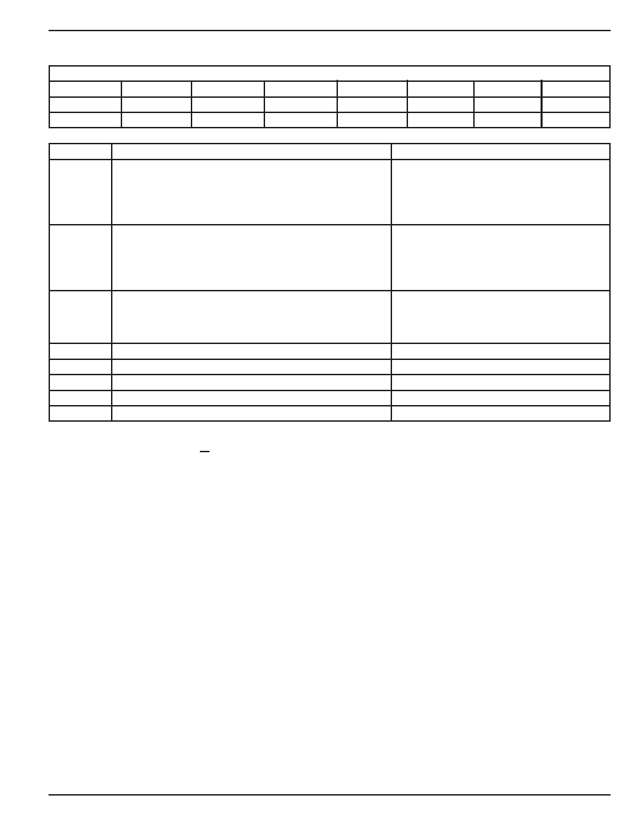
Status Register Slot B (STATB)
8-Bits, Read-Only
Status Register, Slot B (STATB)
D[7]
D[6]
D[5]
D[4]
D[3]
D[2]
D[1]
D[0]
read-only
read/write
read-only
read/write
read-only
read/write
FAULTB
MAINB
VAUXB
VAUXBF
Reserved
12VBF
Reserved
3VBF
Bit(s)
Function
Operation
FAULTB
FAULT Pin Status - Slot B
1 = Fault pin asserted
(/FAULTB pin is LOW)
0 = Fault pin deasserted
(/FAULTB pin is HIGH)
See Notes 1, 2, and 3.
MAINB
MAIN Enable Status - Slot B
Represents the actual state (on/off) of the
four Main Power outputs for Slot B
(+12V and +3.3V)
1 = MAIN Power ON
0 = MAIN Power OFF
VAUXB
VAUX Enable Status - Slot B
Represents the actual state (on/off) of the
Auxiliary Power output for Slot B
1 = AUX Power ON
0 = AUX Power OFF
VAUXBF
Overcurrent Fault: VAUXB supply
1 = Fault 0 = No fault
D[3]
Reserved
Always read as zero
12VBF
Overcurrent Fault: +12V supply
1 = Fault 0 = No fault
D[1]
Reserved
Always read as zero
3VBF
Overcurrent Fault: 3.3V supply
1 = Fault 0 = No fault
Power-Up Default Value:
0000 0000b = 00h
Command_Byte Value (R/W):
0000 0101b = 05h
The power-up default value is 00h. Both slots are disabled upon power-up, i.e., all supply outputs are off. In response to an
overcurrent fault condition, writing a logical 1 back into the active (or set) bit position will clear the bit and deassert /INT. The
status of the /FAULTB pin is not affected by reading the Status Register or by clearing active status bits.
Notes:
1.
If FAULTB has been set by an overcurrent condition on one or more of the MAIN outputs, the ONB input must go LOW to reset FAULTB.
If FAULTB has been set by a VAUXB overcurrent event, the AUXENB input must go LOW to reset FAULTB.
If an overcurrent has occurred on both a MAIN output and the VAUX output of slot B, both ONB and AUXENB of the slot must go low to reset
FAULTB.
2.
Neither the FAULTB bits nor the /FAULTB pins are active when the MIC2591B power paths are controlled by the System Management Interface.
When using SMI power path control, the AUXENB and ONB pins for that slot must be tied to GND.
3:. If /FORCE_ONB is asserted (low), the /FAULTB pin will be unconditionally forced to its open-drain state. Note, though, that the value in the FAULTB
register bit is not affected by /FORCE_ONB, but will instead continue to read as a high if no faults are present on Slot B, and as a low if any fault
conditions exist which would disable Slot B if /FORCE_ONB was not asserted.
D[7]
D[6]
D[5]
D[4]
D[3]
D[2]
D[1]
D[0]
read-only
read/write
read-only
read/write
read-only
read/write
FAULTB
MAINB
VAUXB
VAUXBF
Reserved
12VBF
Reserved
3VBF
FAULTB
FAULT Pin Status - Slot B
1 = Fault pin asserted
(/FAULTB pin is LOW)
0 = Fault pin deasserted
(/FAULTB pin is HIGH)
See Notes 1, 2, and 3.
MAINB
MAIN Enable Status - Slot B
Represents the actual state (on/off) of the
four Main Power outputs for Slot B
(+12V and +3.3V)
1 = MAIN Power ON
0 = MAIN Power OFF
VAUXB
VAUX Enable Status - Slot B
Represents the actual state (on/off) of the
Auxiliary Power output for Slot B
1 = AUX Power ON
0 = AUX Power OFF
VAUXBF
Overcurrent Fault: VAUXB supply
1 = Fault 0 = No fault
D[3]
Reserved
Always read as zero
12VBF
Overcurrent Fault: +12V supply
1 = Fault 0 = No fault
D[1]
Reserved
Always read as zero
3VBF
Overcurrent Fault: 3.3V supply
1 = Fault 0 = No fault
Bit(s)
Function
Operation
FAULTB
FAULT Pin Status - Slot B
1 = Fault pin asserted
(/FAULTB pin is LOW)
0 = Fault pin deasserted
(/FAULTB pin is HIGH)
See Notes 1, 2, and 3.
MAINB
MAIN Enable Status - Slot B
Represents the actual state (on/off) of the
four Main Power outputs for Slot B
(+12V and +3.3V)
1 = MAIN Power ON
0 = MAIN Power OFF
VAUXB
VAUX Enable Status - Slot B
Represents the actual state (on/off) of the
Auxiliary Power output for Slot B
1 = AUX Power ON
0 = AUX Power OFF
VAUXBF
Overcurrent Fault: VAUXB supply
1 = Fault 0 = No fault
D[3]
Reserved
Always read as zero
12VBF
Overcurrent Fault: +12V supply
1 = Fault 0 = No fault
D[1]
Reserved
Always read as zero
3VBF
Overcurrent Fault: 3.3V supply
1 = Fault 0 = No fault
D[7]
D[6]
D[5]
D[4]
D[3]
D[2]
D[1]
D[0]
read-only
read/write
read-only
read/write
read-only
read/write
FAULTB
MAINB
VAUXB
VAUXBF
Reserved
12VBF
Reserved
3VBF
D[7]
D[6]
D[5]
D[4]
D[3]
D[2]
D[1]
D[0]
read-only
read/write
read-only
read/write
read-only
read/write
FAULTB
MAINB
VAUXB
VAUXBF
Reserved
12VBF
Reserved
3VBF
D[7]
D[6]
D[5]
D[4]
D[3]
D[2]
D[1]
D[0]
read-only
read/write
read-only
read/write
read-only
read/write
FAULTB
MAINB
VAUXB
VAUXBF
Reserved
12VBF
Reserved
3VBF
D[7]
D[6]
D[5]
D[4]
D[3]
D[2]
D[1]
D[0]
read-only
read/write
read-only
read/write
read-only
read/write
FAULTB
MAINB
VAUXB
VAUXBF
Reserved
12VBF
Reserved
3VBF
D[7]
D[6]
D[5]
D[4]
D[3]
D[2]
D[1]
D[0]
read-only
read/write
read-only
read/write
read-only
read/write
FAULTB
MAINB
VAUXB
VAUXBF
Reserved
12VBF
Reserved
3VBF
D[7]
D[6]
D[5]
D[4]
D[3]
D[2]
D[1]
D[0]
read-only
read/write
read-only
read/write
read-only
read/write
FAULTB
MAINB
VAUXB
VAUXBF
Reserved
12VBF
Reserved
3VBF
D[7]
D[6]
D[5]
D[4]
D[3]
D[2]
D[1]
D[0]
read-only
read/write
read-only
read/write
read-only
read/write
FAULTB
MAINB
VAUXB
VAUXBF
Reserved
12VBF
Reserved
3VBF
相關(guān)PDF資料 |
PDF描述 |
|---|---|
| MIC30711-5100W-LF3 | 32 CONTACT(S), FEMALE, RIGHT ANGLE TELECOM AND DATACOM CONNECTOR, SOLDER |
| MIC3730-1.8BR | 1.8 V FIXED POSITIVE LDO REGULATOR, 0.5 V DROPOUT, PSSO5 |
| MIC5225-1.5YM5TR | 1.5 V FIXED POSITIVE LDO REGULATOR, 0.45 V DROPOUT, PDSO5 |
| MIC5225-2.5YM5TR | 2.5 V FIXED POSITIVE LDO REGULATOR, 0.45 V DROPOUT, PDSO5 |
| MIC5225-3.3YM5TR | 3.3 V FIXED POSITIVE LDO REGULATOR, 0.45 V DROPOUT, PDSO5 |
相關(guān)代理商/技術(shù)參數(shù) |
參數(shù)描述 |
|---|---|
| MIC2592B-2BTQ | 功能描述:IC CTRLR HOTPLUG PCI DUAL 48TQFP RoHS:否 類別:集成電路 (IC) >> PMIC - 熱交換 系列:- 產(chǎn)品培訓模塊:Obsolescence Mitigation Program 標準包裝:100 系列:- 類型:熱插拔開關(guān) 應(yīng)用:通用 內(nèi)部開關(guān):是 電流限制:可調(diào) 電源電壓:9 V ~ 13.2 V 工作溫度:-40°C ~ 150°C 安裝類型:表面貼裝 封裝/外殼:10-WFDFN 裸露焊盤 供應(yīng)商設(shè)備封裝:10-TDFN-EP(3x3) 包裝:管件 |
| MIC2592B-2BTQ TR | 功能描述:IC PCI HOT PLUG CTLR DUAL 48TQFP RoHS:否 類別:集成電路 (IC) >> PMIC - 熱交換 系列:- 產(chǎn)品培訓模塊:Obsolescence Mitigation Program 標準包裝:100 系列:- 類型:熱插拔開關(guān) 應(yīng)用:通用 內(nèi)部開關(guān):是 電流限制:可調(diào) 電源電壓:9 V ~ 13.2 V 工作溫度:-40°C ~ 150°C 安裝類型:表面貼裝 封裝/外殼:10-WFDFN 裸露焊盤 供應(yīng)商設(shè)備封裝:10-TDFN-EP(3x3) 包裝:管件 |
| MIC2592B-2YTQ | 功能描述:熱插拔功率分布 Dual-slot PCI-Express Hot Swap Power Controller - Lead Free RoHS:否 制造商:Texas Instruments 產(chǎn)品:Controllers & Switches 電流限制: 電源電壓-最大:7 V 電源電壓-最小:- 0.3 V 工作溫度范圍: 功率耗散: 安裝風格:SMD/SMT 封裝 / 箱體:MSOP-8 封裝:Tube |
| MIC2592B-2YTQ TR | 功能描述:熱插拔功率分布 Dual-slot PCI-Express Hot Swap Power Controller - Lead Free RoHS:否 制造商:Texas Instruments 產(chǎn)品:Controllers & Switches 電流限制: 電源電壓-最大:7 V 電源電壓-最小:- 0.3 V 工作溫度范圍: 功率耗散: 安裝風格:SMD/SMT 封裝 / 箱體:MSOP-8 封裝:Tube |
| MIC2593-2BTQ | 功能描述:IC CTRLR HOTPLUG PCI DUAL 48TQFP RoHS:否 類別:集成電路 (IC) >> PMIC - 熱交換 系列:- 產(chǎn)品培訓模塊:Obsolescence Mitigation Program 標準包裝:100 系列:- 類型:熱插拔開關(guān) 應(yīng)用:通用 內(nèi)部開關(guān):是 電流限制:可調(diào) 電源電壓:9 V ~ 13.2 V 工作溫度:-40°C ~ 150°C 安裝類型:表面貼裝 封裝/外殼:10-WFDFN 裸露焊盤 供應(yīng)商設(shè)備封裝:10-TDFN-EP(3x3) 包裝:管件 |
發(fā)布緊急采購,3分鐘左右您將得到回復。