- 您現(xiàn)在的位置:買賣IC網(wǎng) > PDF目錄370849 > M37736EHLXXXHP (Mitsubishi Electric Corporation) PROM VERSION OF M37736MHLXXXHP(MICROCOMPUTERS) PDF資料下載
參數(shù)資料
| 型號: | M37736EHLXXXHP |
| 廠商: | Mitsubishi Electric Corporation |
| 英文描述: | PROM VERSION OF M37736MHLXXXHP(MICROCOMPUTERS) |
| 中文描述: | PROM的版本M37736MHLXXXHP(微型) |
| 文件頁數(shù): | 44/96頁 |
| 文件大?。?/td> | 1328K |
| 代理商: | M37736EHLXXXHP |
第1頁第2頁第3頁第4頁第5頁第6頁第7頁第8頁第9頁第10頁第11頁第12頁第13頁第14頁第15頁第16頁第17頁第18頁第19頁第20頁第21頁第22頁第23頁第24頁第25頁第26頁第27頁第28頁第29頁第30頁第31頁第32頁第33頁第34頁第35頁第36頁第37頁第38頁第39頁第40頁第41頁第42頁第43頁當(dāng)前第44頁第45頁第46頁第47頁第48頁第49頁第50頁第51頁第52頁第53頁第54頁第55頁第56頁第57頁第58頁第59頁第60頁第61頁第62頁第63頁第64頁第65頁第66頁第67頁第68頁第69頁第70頁第71頁第72頁第73頁第74頁第75頁第76頁第77頁第78頁第79頁第80頁第81頁第82頁第83頁第84頁第85頁第86頁第87頁第88頁第89頁第90頁第91頁第92頁第93頁第94頁第95頁第96頁
PRELIMINARY
Notice: This is not a final specification.
Some parametric limits are subject to change.
MITSUBISHI MICROCOMPUTERS
M37736MHBXXXGP
SINGLE-CHIP 16-BIT CMOS MICROCOMPUTER
44
WATCHDOG TIMER
The watchdog timer is used to detect unexpected execution sequence
caused by software runaway.
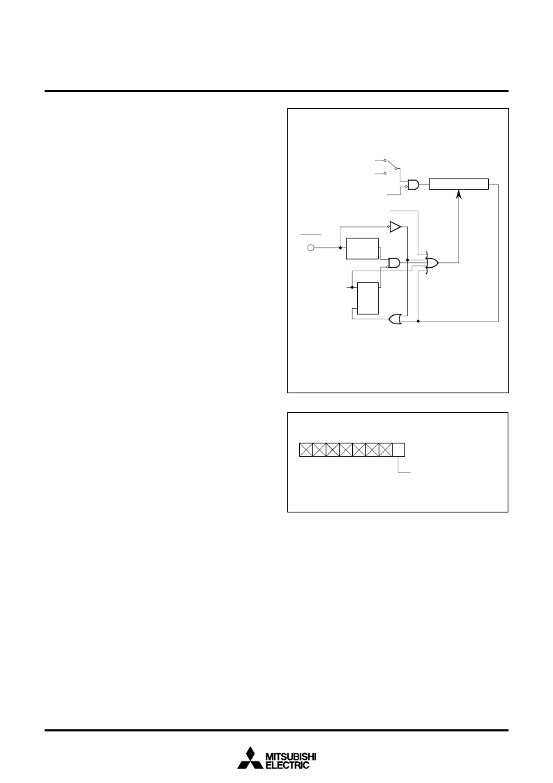
Figure 51 shows a block diagram of the watchdog timer. The watchdog
timer includes a 12-bit binary counter.
The watchdog timer counts divided clock f
32
or f
512
. Whether to count
f
32
or f
512
is determined by the watchdog timer frequency selection
flag shown in Figure 52. For divided clocks f
32
and f
512
, refer to the
section on clock generating circuit. f
512
is selected when the flag is
“0” and f
32
is selected when it is “1”. The flag is cleared after reset.
“FFF
_____
the
RESET
pin, STP instruction is executed, data is written to the
watchdog timer register, or the most significant bit of the watchdog
timer becomes “0”.
After “FFF
16
” is set in the watchdog timer, the contents of the watchdog
timer is decremented by one at every cycle of f
32
or f
512
. After 2048
counts, the most significant bit of the watchdog timer becomes “0”,
and a watchdog timer interrupt request bit is set, and “FFF
16
” is set in
the watchdog timer.
Normally, a program is written so that data is written in the watchdog
timer register before the most significant bit of the watchdog timer
becomes “0”. If this routine is not executed due to unexpected program
runaway, the most significant bit of the watchdog timer becomes
eventually “0” and an interrupt is generated.
The processor can be reset by setting “1” to the software reset bit (bit
3 of the processor mode register 0) described in Figure 10 on the
interrupt section and generating a reset pulse.
_____
The watchdog timer stops its function when the
RESET
pin voltage is
raised to double the Vcc voltage.
The watchdog timer can also be used to recover from when the clock
is stopped by the STP instruction. Refer to the section on stand-by
function for more details.
The watchdog timer hold the contents during a hold state and the
input of the divided clock is stopped.
Fig. 51 Watchdog timer block diagram
Fig. 52 Watchdog timer frequency selection flag
0 : Select f
512
1 : Select f
32
7
61
16
Addresses
Watchdog timer
frequency
selection flag
6
5
4
3
2
1
0
Select with the watchdog timer frequency selection flag.
(If STP instruction is executed, f
32
is forced to be selected when
the system clock selection bit is “0”, or f
8
is forced to be selected
when the system clock selection bit is “1”.)
Set “FFF
16
”
Write to watchdog
timer register
2 Vcc
circuit
S
Q
R
RESET
STP instruction
f
512
f
32
Watchog timer
(Address 60
16
)
Hold
Note.
When the main clock external input selection bit is “1”
and the main clock or the main clock divided by 8 is
selected as a system clock, or the sub-clock external
input selection bit is “1” and the sub-clock is selected;
the divided clock f
16
is input.
(Note)
相關(guān)PDF資料 |
PDF描述 |
|---|---|
| M37736MHLXXXHP | SINGLE-CHIP 16-BIT CMOS MICROCOMPUTER |
| M37736EHBXXXGP | PROM VERSION OF M37736MHBXXXGP(MICROCOMPUTERS) |
| M37736MHBXXXGP | SINGLE-CHIP 16-BIT CMOS MICROCOMPUTER |
| M37753FFCFP | SINGLE CHIP 16 BIT CMOS MICROCOMPUTER FLASH MEMORY VERSION |
| M37753FFCHP | SINGLE CHIP 16 BIT CMOS MICROCOMPUTER FLASH MEMORY VERSION |
相關(guān)代理商/技術(shù)參數(shù) |
參數(shù)描述 |
|---|---|
| M37736M4B | 制造商:MITSUBISHI 制造商全稱:Mitsubishi Electric Semiconductor 功能描述:SINGLE-CHIP 16-BIT CMOS MICROCOMPUTER |
| M37736M4BXXXGP | 制造商:MITSUBISHI 制造商全稱:Mitsubishi Electric Semiconductor 功能描述:SINGLE-CHIP 16-BIT CMOS MICROCOMPUTER |
| M37736M4L | 制造商:MITSUBISHI 制造商全稱:Mitsubishi Electric Semiconductor 功能描述:SINGLE-CHIP 16-BIT CMOS MICROCOMPUTER |
| M37736M4LXXXHP | 制造商:MITSUBISHI 制造商全稱:Mitsubishi Electric Semiconductor 功能描述:SINGLE-CHIP 16-BIT CMOS MICROCOMPUTER |
| M37736MHB | 制造商:MITSUBISHI 制造商全稱:Mitsubishi Electric Semiconductor 功能描述:SINGLE-CHIP 16-BIT CMOS MICROCOMPUTER |
發(fā)布緊急采購,3分鐘左右您將得到回復(fù)。