- 您現(xiàn)在的位置:買賣IC網(wǎng) > PDF目錄1915 > DS31256+ (Maxim Integrated Products)IC CTRLR HDLC 256-CHANNEL 256BGA PDF資料下載
參數(shù)資料
| 型號: | DS31256+ |
| 廠商: | Maxim Integrated Products |
| 文件頁數(shù): | 169/183頁 |
| 文件大小: | 0K |
| 描述: | IC CTRLR HDLC 256-CHANNEL 256BGA |
| 產(chǎn)品培訓(xùn)模塊: | Lead (SnPb) Finish for COTS Obsolescence Mitigation Program |
| 標(biāo)準(zhǔn)包裝: | 40 |
| 控制器類型: | HDLC 控制器 |
| 接口: | 串行 |
| 電源電壓: | 3 V ~ 3.6 V |
| 電流 - 電源: | 500mA |
| 工作溫度: | 0°C ~ 70°C |
| 安裝類型: | 表面貼裝 |
| 封裝/外殼: | 256-BBGA |
| 供應(yīng)商設(shè)備封裝: | 256-BGA(27x27) |
| 包裝: | 管件 |
第1頁第2頁第3頁第4頁第5頁第6頁第7頁第8頁第9頁第10頁第11頁第12頁第13頁第14頁第15頁第16頁第17頁第18頁第19頁第20頁第21頁第22頁第23頁第24頁第25頁第26頁第27頁第28頁第29頁第30頁第31頁第32頁第33頁第34頁第35頁第36頁第37頁第38頁第39頁第40頁第41頁第42頁第43頁第44頁第45頁第46頁第47頁第48頁第49頁第50頁第51頁第52頁第53頁第54頁第55頁第56頁第57頁第58頁第59頁第60頁第61頁第62頁第63頁第64頁第65頁第66頁第67頁第68頁第69頁第70頁第71頁第72頁第73頁第74頁第75頁第76頁第77頁第78頁第79頁第80頁第81頁第82頁第83頁第84頁第85頁第86頁第87頁第88頁第89頁第90頁第91頁第92頁第93頁第94頁第95頁第96頁第97頁第98頁第99頁第100頁第101頁第102頁第103頁第104頁第105頁第106頁第107頁第108頁第109頁第110頁第111頁第112頁第113頁第114頁第115頁第116頁第117頁第118頁第119頁第120頁第121頁第122頁第123頁第124頁第125頁第126頁第127頁第128頁第129頁第130頁第131頁第132頁第133頁第134頁第135頁第136頁第137頁第138頁第139頁第140頁第141頁第142頁第143頁第144頁第145頁第146頁第147頁第148頁第149頁第150頁第151頁第152頁第153頁第154頁第155頁第156頁第157頁第158頁第159頁第160頁第161頁第162頁第163頁第164頁第165頁第166頁第167頁第168頁當(dāng)前第169頁第170頁第171頁第172頁第173頁第174頁第175頁第176頁第177頁第178頁第179頁第180頁第181頁第182頁第183頁
DS31256 256-Channel, High-Throughput HDLC Controller
86 of 183
On an HDLC-channel basis in the receive DMA configuration RAM, the host instructs the DMA how to
use the large and small buffers for the incoming packet data on that particular HDLC channel. The host
has three options: (1) only use large buffers, (2) only use small buffers, or (3) first fill a small buffer,
then, if the incoming packet requires more buffer space, use one or more large buffers for the remainder
of the packet. The host selects the option through the size field in the receive configuration RAM
(Section 9.2.5). Large buffers are best used for data-intensive, time-insensitive packets like graphics
files, whereas small buffers are best used for time-sensitive information like real-time voice.
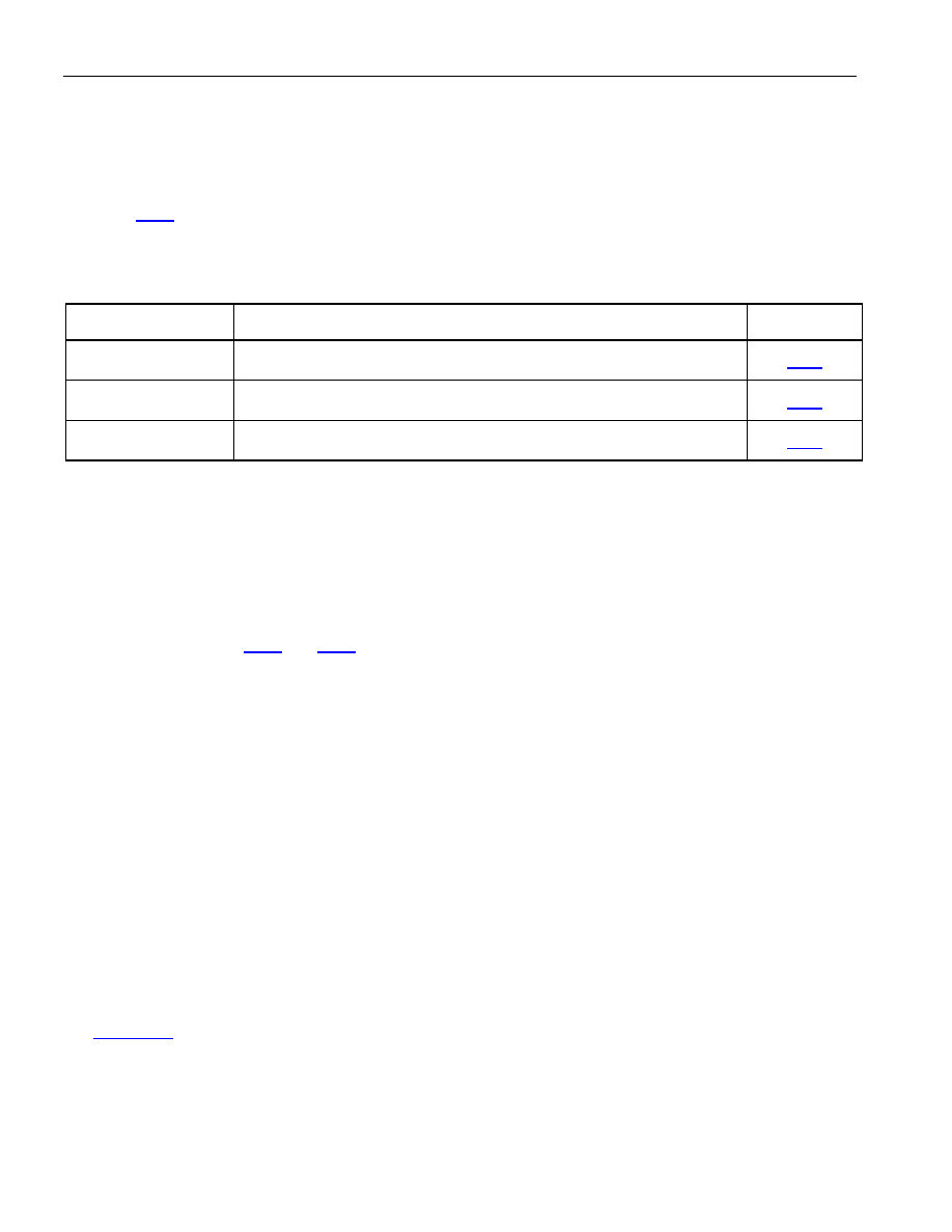
Table 9-B. Receive DMA Main Operational Areas
DESCRIPTORS
FUNCTION
SECTION
Packet
A dedicated area of memory that describes the location and attributes of
the packet data.
Free Queue
A dedicated area of memory that the host writes to inform the DMA
where to store incoming packet data.
Done Queue
A dedicated area of memory that the DMA writes to inform the host
that the packet data is ready for processing.
The done-queue descriptors contain information that the DMA wishes to pass to the host. Through the
done-queue descriptors, the DMA informs the host about the incoming packet data and where to find the
packet descriptors that it has written into main memory. Each completed descriptor contains the starting
address of the data buffer where the packet data is stored.
If enabled, the DMA can burst read the free-queue descriptors and burst write the done-queue
descriptors. This helps minimize PCI bus accesses, freeing the PCI bus up to do more time critical
Receive DMA Actions
A typical scenario for the receive DMA is as follows:
1) The receive DMA gets a request from the receive FIFO that it has packet data that needs to be sent to
the PCI bus.
2) The receive DMA determines whether the incoming packet data should be stored in a large buffer or
a small buffer.
3) The receive DMA then reads a free-queue descriptor (either by reading a single descriptor or a burst
of descriptors), indicating where, in main memory, there exists some free data buffer space and
where the associated free packet descriptor resides.
4) The receive DMA starts storing packet data in the previously free buffer data space by writing it out
through the PCI bus.
5) When the receive DMA realizes that the current data buffer is filled (by knowing the buffer size it
can calculate this), it then reads another free-queue descriptor to find another free data buffer and
packet descriptor location.
6) The receive DMA then writes the previous packet descriptor and creates a linked list by placing the
current descriptor in the next descriptor pointer field; it then starts filling the new buffer location.
Figure 9-1 provides an example of packet descriptors being link listed together (see channel 2).
7) This continues until the entire packet data is stored.
8) The receive DMA either waits until a packet has been completely received or until a programmable
number (from 1 to 7) of data buffers have been filled before writing the done-queue descriptor, which
indicates to the host that packet data is ready for processing.
相關(guān)PDF資料 |
PDF描述 |
|---|---|
| DS3141+ | IC FRAMER DS3/E3 SNGL 144CSBGA |
| DS31412N | IC 12CH DS3/3 FRAMER 349-BGA |
| DS3150TN | IC LIU T3/E3/STS-1 IND 48-TQFP |
| DS3154N+ | IC LIU DS3/E3/STS-1 QD 144CSBGA |
| DS3164+ | IC ATM/PACKET PHY QUAD 400-BGA |
相關(guān)代理商/技術(shù)參數(shù) |
參數(shù)描述 |
|---|---|
| DS31256+ | 功能描述:輸入/輸出控制器接口集成電路 256Ch High Thruput HDLC Cntlr RoHS:否 制造商:Silicon Labs 產(chǎn)品: 輸入/輸出端數(shù)量: 工作電源電壓: 最大工作溫度:+ 85 C 最小工作溫度:- 40 C 安裝風(fēng)格:SMD/SMT 封裝 / 箱體:QFN-64 封裝:Tray |
| DS31256B | 功能描述:輸入/輸出控制器接口集成電路 256Ch High Thruput HDLC Cntlr RoHS:否 制造商:Silicon Labs 產(chǎn)品: 輸入/輸出端數(shù)量: 工作電源電壓: 最大工作溫度:+ 85 C 最小工作溫度:- 40 C 安裝風(fēng)格:SMD/SMT 封裝 / 箱體:QFN-64 封裝:Tray |
| DS31256DK | 功能描述:網(wǎng)絡(luò)開發(fā)工具 RoHS:否 制造商:Rabbit Semiconductor 產(chǎn)品:Development Kits 類型:Ethernet to Wi-Fi Bridges 工具用于評估:RCM6600W 數(shù)據(jù)速率:20 Mbps, 40 Mbps 接口類型:802.11 b/g, Ethernet 工作電源電壓:3.3 V |
| DS31256-W+ | 制造商:Maxim Integrated Products 功能描述:ENVOY 256 CHANNEL HDLC - WAIVER - Rail/Tube |
| DS312BNC | 制造商:未知廠家 制造商全稱:未知廠家 功能描述:Industrial Control IC |
發(fā)布緊急采購,3分鐘左右您將得到回復(fù)。