- 您現(xiàn)在的位置:買賣IC網(wǎng) > PDF目錄1915 > DS31256+ (Maxim Integrated Products)IC CTRLR HDLC 256-CHANNEL 256BGA PDF資料下載
參數(shù)資料
| 型號(hào): | DS31256+ |
| 廠商: | Maxim Integrated Products |
| 文件頁(yè)數(shù): | 134/183頁(yè) |
| 文件大小: | 0K |
| 描述: | IC CTRLR HDLC 256-CHANNEL 256BGA |
| 產(chǎn)品培訓(xùn)模塊: | Lead (SnPb) Finish for COTS Obsolescence Mitigation Program |
| 標(biāo)準(zhǔn)包裝: | 40 |
| 控制器類型: | HDLC 控制器 |
| 接口: | 串行 |
| 電源電壓: | 3 V ~ 3.6 V |
| 電流 - 電源: | 500mA |
| 工作溫度: | 0°C ~ 70°C |
| 安裝類型: | 表面貼裝 |
| 封裝/外殼: | 256-BBGA |
| 供應(yīng)商設(shè)備封裝: | 256-BGA(27x27) |
| 包裝: | 管件 |
第1頁(yè)第2頁(yè)第3頁(yè)第4頁(yè)第5頁(yè)第6頁(yè)第7頁(yè)第8頁(yè)第9頁(yè)第10頁(yè)第11頁(yè)第12頁(yè)第13頁(yè)第14頁(yè)第15頁(yè)第16頁(yè)第17頁(yè)第18頁(yè)第19頁(yè)第20頁(yè)第21頁(yè)第22頁(yè)第23頁(yè)第24頁(yè)第25頁(yè)第26頁(yè)第27頁(yè)第28頁(yè)第29頁(yè)第30頁(yè)第31頁(yè)第32頁(yè)第33頁(yè)第34頁(yè)第35頁(yè)第36頁(yè)第37頁(yè)第38頁(yè)第39頁(yè)第40頁(yè)第41頁(yè)第42頁(yè)第43頁(yè)第44頁(yè)第45頁(yè)第46頁(yè)第47頁(yè)第48頁(yè)第49頁(yè)第50頁(yè)第51頁(yè)第52頁(yè)第53頁(yè)第54頁(yè)第55頁(yè)第56頁(yè)第57頁(yè)第58頁(yè)第59頁(yè)第60頁(yè)第61頁(yè)第62頁(yè)第63頁(yè)第64頁(yè)第65頁(yè)第66頁(yè)第67頁(yè)第68頁(yè)第69頁(yè)第70頁(yè)第71頁(yè)第72頁(yè)第73頁(yè)第74頁(yè)第75頁(yè)第76頁(yè)第77頁(yè)第78頁(yè)第79頁(yè)第80頁(yè)第81頁(yè)第82頁(yè)第83頁(yè)第84頁(yè)第85頁(yè)第86頁(yè)第87頁(yè)第88頁(yè)第89頁(yè)第90頁(yè)第91頁(yè)第92頁(yè)第93頁(yè)第94頁(yè)第95頁(yè)第96頁(yè)第97頁(yè)第98頁(yè)第99頁(yè)第100頁(yè)第101頁(yè)第102頁(yè)第103頁(yè)第104頁(yè)第105頁(yè)第106頁(yè)第107頁(yè)第108頁(yè)第109頁(yè)第110頁(yè)第111頁(yè)第112頁(yè)第113頁(yè)第114頁(yè)第115頁(yè)第116頁(yè)第117頁(yè)第118頁(yè)第119頁(yè)第120頁(yè)第121頁(yè)第122頁(yè)第123頁(yè)第124頁(yè)第125頁(yè)第126頁(yè)第127頁(yè)第128頁(yè)第129頁(yè)第130頁(yè)第131頁(yè)第132頁(yè)第133頁(yè)當(dāng)前第134頁(yè)第135頁(yè)第136頁(yè)第137頁(yè)第138頁(yè)第139頁(yè)第140頁(yè)第141頁(yè)第142頁(yè)第143頁(yè)第144頁(yè)第145頁(yè)第146頁(yè)第147頁(yè)第148頁(yè)第149頁(yè)第150頁(yè)第151頁(yè)第152頁(yè)第153頁(yè)第154頁(yè)第155頁(yè)第156頁(yè)第157頁(yè)第158頁(yè)第159頁(yè)第160頁(yè)第161頁(yè)第162頁(yè)第163頁(yè)第164頁(yè)第165頁(yè)第166頁(yè)第167頁(yè)第168頁(yè)第169頁(yè)第170頁(yè)第171頁(yè)第172頁(yè)第173頁(yè)第174頁(yè)第175頁(yè)第176頁(yè)第177頁(yè)第178頁(yè)第179頁(yè)第180頁(yè)第181頁(yè)第182頁(yè)第183頁(yè)

DS31256 256-Channel, High-Throughput HDLC Controller
54 of 183
Bits 8 to 15/Transmit DS0 Data (TDATA). This register holds the most current DS0 byte transmitted. It is used
by the receive-side Layer 1 state machine when channelized local loopback (CLLB) is enabled.
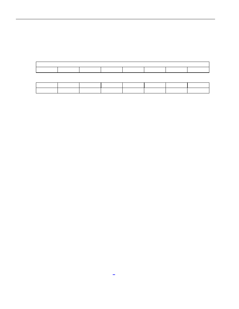
Register Name:
R[n]CFG[j] where n = 0 to 15 for each port and j = 0 to 127 for each DS0
Register Description:
Receive Layer 1 Configuration Register
Register Address:
Indirect Access through CP[n]RD
Bit #
7
6
5
4
3
2
1
0
Name
RCH#(8): Receive HDLC Channel Number
Default
Bit #
15
14
13
12
11
10
9
8
Name
RCHEN
RBERT
n/a
RV54
n/a
CLLB
n/a
R56
Default
Note: Bits that are underlined are read-only; all other bits are read-write.
Bits 0 to 7/Receive Channel Number (RCH#). The CPU loads the number of the HDLC channels associated
with this particular DS0 channel. If the port is running in an unchannelized mode (RUEN = 1), the HDLC channel
number only needs to be loaded into R[n]CFG0. If the fast (52Mbps) HDLC engine is enabled on port 0, HDLC
channel 1 is assigned to it and, likewise, HDLC channel 2 is assigned to the fast HDLC engine on port 2, if it is
enabled. Therefore, these HDLC channel numbers should not be used if the fast HDLC engines are enabled.
00000000 (00h) = HDLC channel number 1 (also used for the fast HDLC engine on port 0)
00000001 (01h) = HDLC channel number 2 (also used for the fast HDLC engine on port 1)
00000010 (02h) = HDLC channel number 3 (also used for the fast HDLC engine on port 2)
00000011 (03h) = HDLC channel number 4
11111111 (FFh) = HDLC channel number 256
Bit 8/Receive 56kbps (R56). If the port is running a channelized application, this bit determines whether the LSB
of each DS0 should be processed or not. If this bit is set, the LSB of each DS0 channel is not routed to the HDLC
controller (or the BERT, if it has been enabled through the RBERT bit). This bit does not affect the operation of
the V.54 detector. It always searches on all 8 bits in the DS0.
0 = 64kbps (use all 8 bits in the DS0)
1 = 56kbps (use only the first 7 bits received in the DS0)
Bit 10/Channelized Local Loopback Enable (CLLB). Enabling this loopback forces the transmit data to replace
the receive data. This bit must be set for each and every DS0 channel that is to be looped back. In order for the
loopback to become active, the DS0 channel must be enabled (RCHEN = 1) and the DS0 channel must be set into
the 64kbps mode (R56 = 0).
0 = loopback disabled
1 = loopback enabled
Bit 12/Receive V.54 Enable (RV54E). If this bit is cleared, this DS0 channel is not examined to check if the V.54
loop pattern is present. If set, the DS0 is examined for the V.54 loop pattern. When searching for the V.54 pattern
within a DS0 channel, all 8 bits of the DS0 channel are examined, regardless of how the DS0 channel is
configured (i.e., 64k or 56k).
0 = do not examine this DS0 channel for the V.54 loop pattern
1 = examine this DS0 channel for the V.54 loop pattern
Bit 14/Route Data Into BERT (RBERT). Setting this bit routes the DS0 data into the BERT function. If the DS0
channel has been configured for 56kbps operation (R56 = 1), the LSB of each DS0 channel is not routed to the
BERT block. In order for the data to make it to the BERT block, the host must also configure the BERT for the
proper port through the master control register (Section 5).
0 = do not route data to BERT
1 = route data to BERT
相關(guān)PDF資料 |
PDF描述 |
|---|---|
| DS3141+ | IC FRAMER DS3/E3 SNGL 144CSBGA |
| DS31412N | IC 12CH DS3/3 FRAMER 349-BGA |
| DS3150TN | IC LIU T3/E3/STS-1 IND 48-TQFP |
| DS3154N+ | IC LIU DS3/E3/STS-1 QD 144CSBGA |
| DS3164+ | IC ATM/PACKET PHY QUAD 400-BGA |
相關(guān)代理商/技術(shù)參數(shù) |
參數(shù)描述 |
|---|---|
| DS31256+ | 功能描述:輸入/輸出控制器接口集成電路 256Ch High Thruput HDLC Cntlr RoHS:否 制造商:Silicon Labs 產(chǎn)品: 輸入/輸出端數(shù)量: 工作電源電壓: 最大工作溫度:+ 85 C 最小工作溫度:- 40 C 安裝風(fēng)格:SMD/SMT 封裝 / 箱體:QFN-64 封裝:Tray |
| DS31256B | 功能描述:輸入/輸出控制器接口集成電路 256Ch High Thruput HDLC Cntlr RoHS:否 制造商:Silicon Labs 產(chǎn)品: 輸入/輸出端數(shù)量: 工作電源電壓: 最大工作溫度:+ 85 C 最小工作溫度:- 40 C 安裝風(fēng)格:SMD/SMT 封裝 / 箱體:QFN-64 封裝:Tray |
| DS31256DK | 功能描述:網(wǎng)絡(luò)開發(fā)工具 RoHS:否 制造商:Rabbit Semiconductor 產(chǎn)品:Development Kits 類型:Ethernet to Wi-Fi Bridges 工具用于評(píng)估:RCM6600W 數(shù)據(jù)速率:20 Mbps, 40 Mbps 接口類型:802.11 b/g, Ethernet 工作電源電壓:3.3 V |
| DS31256-W+ | 制造商:Maxim Integrated Products 功能描述:ENVOY 256 CHANNEL HDLC - WAIVER - Rail/Tube |
| DS312BNC | 制造商:未知廠家 制造商全稱:未知廠家 功能描述:Industrial Control IC |
發(fā)布緊急采購(gòu),3分鐘左右您將得到回復(fù)。