- 您現(xiàn)在的位置:買賣IC網(wǎng) > PDF目錄166631 > BU-65527M4-200 (DATA DEVICE CORP) 4 CHANNEL(S), MIL-STD-1553 CONTROLLER, XMA PDF資料下載
參數(shù)資料
| 型號(hào): | BU-65527M4-200 |
| 廠商: | DATA DEVICE CORP |
| 元件分類: | 微控制器/微處理器 |
| 英文描述: | 4 CHANNEL(S), MIL-STD-1553 CONTROLLER, XMA |
| 文件頁數(shù): | 7/32頁 |
| 文件大?。?/td> | 2094K |
| 代理商: | BU-65527M4-200 |
第1頁第2頁第3頁第4頁第5頁第6頁當(dāng)前第7頁第8頁第9頁第10頁第11頁第12頁第13頁第14頁第15頁第16頁第17頁第18頁第19頁第20頁第21頁第22頁第23頁第24頁第25頁第26頁第27頁第28頁第29頁第30頁第31頁第32頁
15
Data Device Corporation
www.ddc-web.com
BU-65528 and BU-65527
F1 web-10/02-0
all transmit, receive, and broadcast subaddresses. In the Single
Message mode (also in the Double-Buffer and Circular-Buffer
modes), there is a global-double-buffering scheme, controlled by
bit 13 of Configuration Register #1. This selects from between
the two sets of the various data structures shown in the figure:
the Stack Pointers (fixed addresses), Descriptor Stacks (user
defined addresses), RT Lookup Tables (fixed addresses), and
RT Data Word blocks (user defined addresses). FIGURES 5, 6,
and 7 delineate the “active” and “non-active” areas by the non-
shaded and shaded areas, respectively.
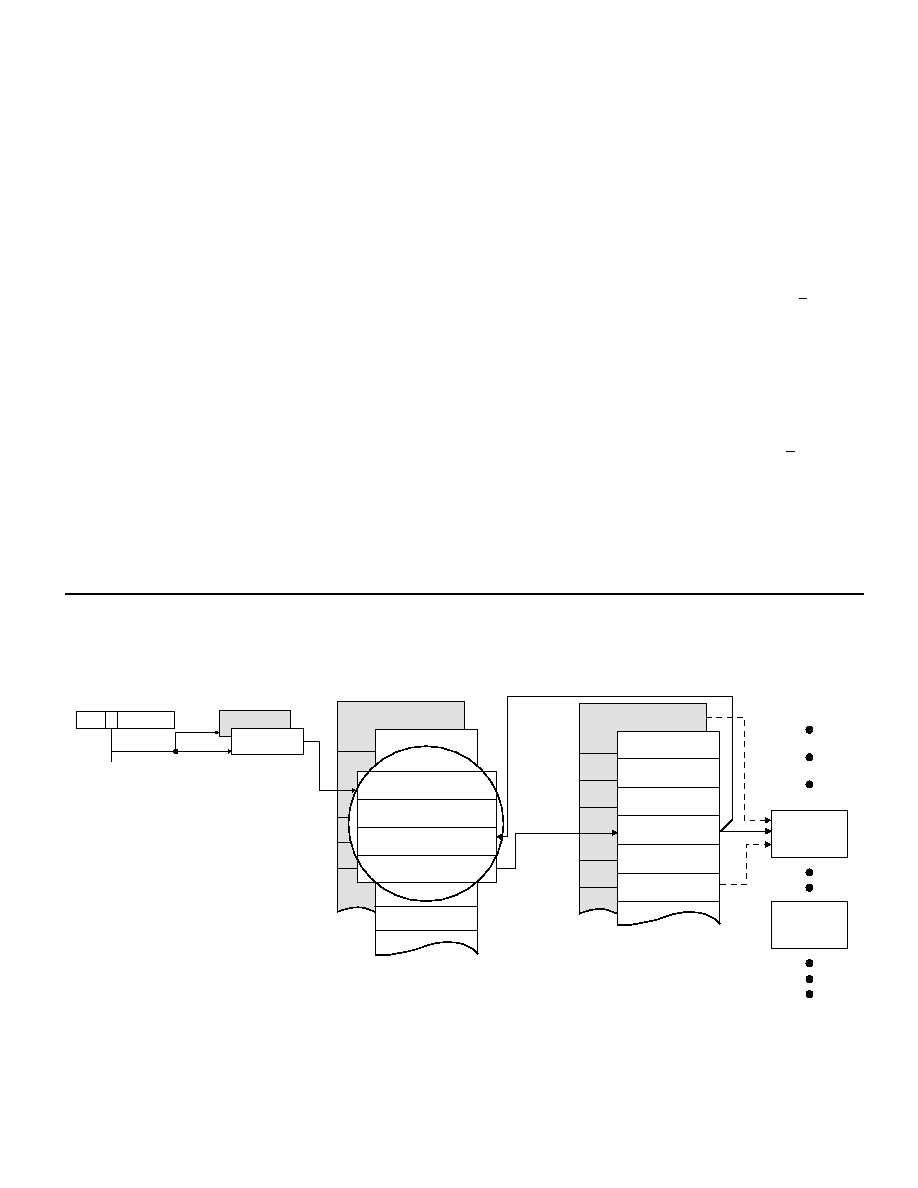
As shown, the ACE stores the Command Word from each mes-
sage received, in the fourth location within the message descrip-
tor (in the stack) for the respective message. The
bit, sub-
address field, and (optionally) broadcast/own address, index into
the active area Lookup Table, to locate the data block pointer for
the current message. The BU-65528/27 RT memory manage-
ment logic then accesses the data block pointer to locate the
starting address for the Data Word block for the current mes-
sage. The maximum size for an RT Data Word block is 32 words.
If a particular subaddress is set to the Single Message mode,
there is a possibility that the contents of the receive data block
may be overwritten or that the transmit data block may be over-
read. In the single message mode it is possible to access multi-
ple data blocks for the same subaddress. This, however, requires
the intervention of the host processor to update the respective
lookup table pointer. The Circular buffering mode, on the other
R
/
T
The fourth section of each of the RT Lookup Tables stores the 32
Subaddress Control Words (refer to TABLE 17 and TABLE 36).
The individual Subaddress Control Words may be used to select
the RT memory management option and interrupt scheme for
each transmit, receive, and (optionally) broadcast subaddress.
For each transmit subaddress, there are two possible memory
management schemes: (1) single message; and (2) circular
buffer. For each receive (and optionally broadcast) subaddress,
there are three possible memory management schemes: (1) sin-
gle message; (2) double buffered; and (3) circular buffer. For
each transmit, receive and broadcast subaddress, there are two
interrupt conditions programmable by the respective Subaddress
Control Word: (1) after every message to the subaddress; (2)
after a circular buffer rollover. An additional table in RAM may be
used to enable interrupts following selected mode code mes-
sages.
When using the circular buffer scheme for a given subaddress,
the size of the circular buffer is programmable by three bits of the
Subaddress Control Word (see TABLE 36). The options for cir-
cular buffer size are 128, 256, 512, 1024, 2048, 4096, and 8192
Data Words.
SINGLE MESSAGE MODE
FIGURE 5 illustrates the RT Single Message memory manage-
ment scheme. When operating the BU-65528/27 in its “AIM-HY”
(default) mode, the Single Message scheme is implemented for
DATA
BLOCKS
DATA BLOCK
BLOCK STATUS WORD
TIME TAG WORD
DATA BLOCK POINTER
RECEIVED COMMAND
WORD
DESCRIPTOR
STACKS
LOOK-UP
TABLE ADDR
LOOK-UP TABLE
(DATA BLOCK ADDR)
15
13
0
CURRENT
AREA B/A
CONFIGURATION
REGISTER
STACK
POINTERS
FIGURE 5. RT MEMORY MANAGEMENT: SINGLE MESSAGE MODE
相關(guān)PDF資料 |
PDF描述 |
|---|---|
| BU-65527C3-300 | 3 CHANNEL(S), MIL-STD-1553 CONTROLLER, XMA |
| BU-65743F3-300 | 2 CHANNEL(S), 1M bps, MIL-STD-1553 CONTROLLER, CQFP80 |
| BU-65863F3-310 | 2 CHANNEL(S), 1M bps, MIL-STD-1553 CONTROLLER, CQFP80 |
| BU-65743F3-200 | 2 CHANNEL(S), 1M bps, MIL-STD-1553 CONTROLLER, CQFP80 |
| BU-65863F3-220 | 2 CHANNEL(S), 1M bps, MIL-STD-1553 CONTROLLER, CQFP80 |
相關(guān)代理商/技術(shù)參數(shù) |
參數(shù)描述 |
|---|---|
| BU6554GVW | 制造商:ROHM 制造商全稱:Rohm 功能描述:Home Electronics and Security Devices IC |
| BU-65-6 | 功能描述:測(cè)試電夾 ALLIGATOR CLIP BLU RoHS:否 制造商:Pomona Electronics 類型:Minigrabber clip 顏色:Black |
| BU-656-0 | 功能描述:測(cè)試電夾 Black Safety Alligat RoHS:否 制造商:Pomona Electronics 類型:Minigrabber clip 顏色:Black |
| BU65612P0-100 | 制造商:未知廠家 制造商全稱:未知廠家 功能描述:Telecommunication IC |
| BU65612P0-110 | 制造商:未知廠家 制造商全稱:未知廠家 功能描述:Telecommunication IC |
發(fā)布緊急采購,3分鐘左右您將得到回復(fù)。