- 您現(xiàn)在的位置:買賣IC網(wǎng) > PDF目錄166631 > BU-65527M4-200 (DATA DEVICE CORP) 4 CHANNEL(S), MIL-STD-1553 CONTROLLER, XMA PDF資料下載
參數(shù)資料
| 型號: | BU-65527M4-200 |
| 廠商: | DATA DEVICE CORP |
| 元件分類: | 微控制器/微處理器 |
| 英文描述: | 4 CHANNEL(S), MIL-STD-1553 CONTROLLER, XMA |
| 文件頁數(shù): | 13/32頁 |
| 文件大?。?/td> | 2094K |
| 代理商: | BU-65527M4-200 |
第1頁第2頁第3頁第4頁第5頁第6頁第7頁第8頁第9頁第10頁第11頁第12頁當(dāng)前第13頁第14頁第15頁第16頁第17頁第18頁第19頁第20頁第21頁第22頁第23頁第24頁第25頁第26頁第27頁第28頁第29頁第30頁第31頁第32頁
20
Data Device Corporation
www.ddc-web.com
BU-65528 and BU-65527
F1 web-10/02-0
Monitor Data Stack B
2000-2FFF
Monitor Command Stack Pointer B (fixed location)
Monitor Data Stack A
1000-1FFF
Not Used
0C00-0FFF
Monitor Command Stack B
0800-0BFF
Monitor Command Stack A
0400-07FF
Not Used
0300-03FF
Selective Monitor Lookup Table (fixed area)
0280-02FF
Not Used
0108-027F
Monitor Data Stack B (fixed location)
0107
Not Used
0104-0105
Monitor Data Stack A (fixed location)
0103
Monitor Command Stack Pointer A (fixed location)
0102
Not Used
0000-0101
DESCRIPTION
ADDRESS
(HEX)
0106
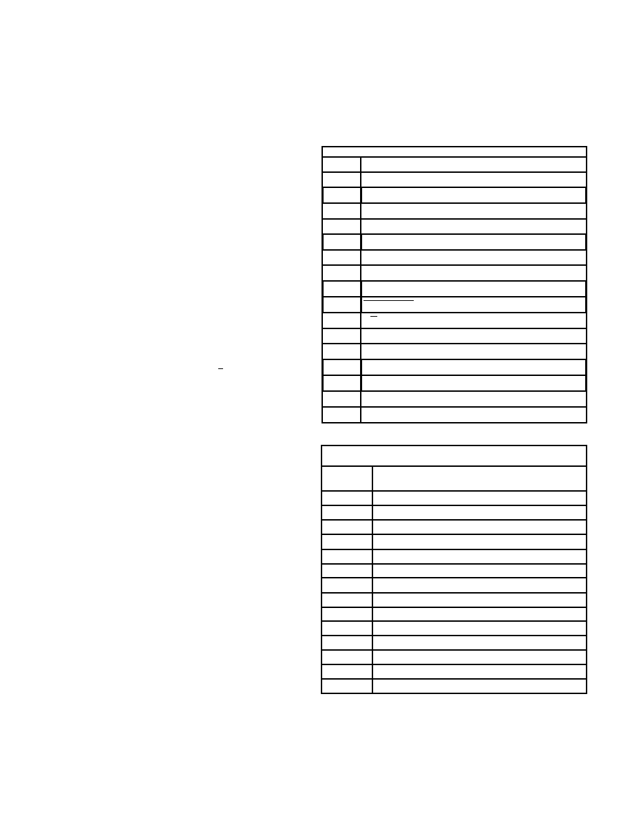
TABLE 38. TYPICAL SELECTIVE MESSAGE MONITOR MEMORY
MAP (shown for 12K RAM)
SIMULTANEOUS RT/MESSAGE MONITOR MODE
The Selective Message Monitor may function as a purely passive
monitor or may be programmed to function as a simultaneous
RT/Monitor. The RT/Monitor mode provides complete Remote
Terminal (RT) operation for the BU-65528/27's strapped RT
address and bus monitor capability for the other 30 non-broad-
cast RT addresses. This allows the BU-65528/27 to simultane-
ously operate as a full function RT and “snoop” on all or a sub-
set of the bus activity involving the other RTs on a bus. This type
of operation is sometimes needed to implement a backup bus
controller. The combined RT/Selective Monitor maintains three
stack areas in the BU-65528/27 address space: an RT
Command Stack, a Monitor Command Stack, and a Monitor
Data Stack. The pointers for the various stacks have fixed loca-
tions in the BU-65528/27 address space.
SELECTIVE MESSAGE MONITOR MEMORY
ORGANIZATION
TABLE 38 illustrates a typical memory map for the ACE in the
Selective Message Monitor mode. This mode of operation
defines several fixed locations in the RAM. These locations allo-
cate in a manner that is compatible with the combined
RT/Selective Message Monitor mode. The fixed memory map
consists of two Monitor Command Stack Pointers (locations
102h and 106h), two Monitor Data Stack Pointers (locations
103h and 107h), and a Selective Message Monitor Lookup Table
(0280-02FFh) based on RT Address,
, and subaddress.
Assume a Monitor Command Stack size of 1K words, and a
Monitor Data Stack size of 2K words.
Refer to FIGURE 8 for an illustration of the Selective Message
Monitor operation. Upon receipt of a valid Command Word, the
BU-65528/27 will reference the Selective Monitor Lookup Table
(a fixed block of addresses) to check for the condition (dis-
abled/enabled) of the current command. If disabled, the BU-
65528/27 will ignore (and not store) the current message; if
enabled, the BU-65528/27 will create an entry in the Monitor
Command Stack at the address location referenced by the
Monitor Command Stack Pointer.
Similar to RT mode, The ACE stores a Block Status Word, 16-bit
Time Tag Word, and Data Block Pointer in the Message
Descriptor, along with the received 1553 Command Word follow-
ing reception of the Command Word. The ACE writes the Block
Status and Time Tag Words at both the start and end of the mes-
sage. The Monitor Block Status Word contains indications of
message in-progress or message complete, bus channel,
Monitor Data Stack Rollover, RT-to-RT transfer and RT-to-RT
transfer errors, message format error, and other error conditions.
TABLE 32 shows the Message Monitor Block Status Word. The
Data Block Pointer references the first word stored in the Monitor
Data Stack (the first word following the Command Word) for the
current message. The BU-65528/27 will then proceed to store
the subsequent words from the message (possible second
Command Word, Data Word(s), Status Word(s)) into consecutive
locations in the Monitor Data Stack.
The size of the Monitor Command Stack is programmable to
256, 1K, 4K, or 16K words. The Monitor Data Stack size is pro-
grammable to 512, 1K, 2K, 4K, 8K, 16K, 32K, or 64K words.
R
/
T
WC4/MC4
0(LSB)
SA0
1
SA1
2
0
SA2
3
SA3
4
SA4
5
T/R
6
BROADCAST/OWN ADDRESS
7
1
8
1
9
0
10
0
12
0
13
0
14
0
15(MSB)
DESCRIPTION
BIT
11
TABLE 37. ILLEGALIZING RAM ADDRESS DEFINITION
Monitor interrupts may be enabled for Monitor Command Stack
Rollover, Monitor Data Stack Rollover, and/or End-of-Message
conditions. In addition, in the Word Monitor mode there may be
an interrupt enabled for a Monitor Trigger condition.
相關(guān)PDF資料 |
PDF描述 |
|---|---|
| BU-65527C3-300 | 3 CHANNEL(S), MIL-STD-1553 CONTROLLER, XMA |
| BU-65743F3-300 | 2 CHANNEL(S), 1M bps, MIL-STD-1553 CONTROLLER, CQFP80 |
| BU-65863F3-310 | 2 CHANNEL(S), 1M bps, MIL-STD-1553 CONTROLLER, CQFP80 |
| BU-65743F3-200 | 2 CHANNEL(S), 1M bps, MIL-STD-1553 CONTROLLER, CQFP80 |
| BU-65863F3-220 | 2 CHANNEL(S), 1M bps, MIL-STD-1553 CONTROLLER, CQFP80 |
相關(guān)代理商/技術(shù)參數(shù) |
參數(shù)描述 |
|---|---|
| BU6554GVW | 制造商:ROHM 制造商全稱:Rohm 功能描述:Home Electronics and Security Devices IC |
| BU-65-6 | 功能描述:測試電夾 ALLIGATOR CLIP BLU RoHS:否 制造商:Pomona Electronics 類型:Minigrabber clip 顏色:Black |
| BU-656-0 | 功能描述:測試電夾 Black Safety Alligat RoHS:否 制造商:Pomona Electronics 類型:Minigrabber clip 顏色:Black |
| BU65612P0-100 | 制造商:未知廠家 制造商全稱:未知廠家 功能描述:Telecommunication IC |
| BU65612P0-110 | 制造商:未知廠家 制造商全稱:未知廠家 功能描述:Telecommunication IC |
發(fā)布緊急采購,3分鐘左右您將得到回復(fù)。