- 您現(xiàn)在的位置:買賣IC網(wǎng) > PDF目錄373972 > AD9984APCBZ (Analog Devices, Inc.) High Performance 10-Bit Display Interface PDF資料下載
參數(shù)資料
| 型號: | AD9984APCBZ |
| 廠商: | Analog Devices, Inc. |
| 英文描述: | High Performance 10-Bit Display Interface |
| 中文描述: | 高性能10位顯示接口 |
| 文件頁數(shù): | 26/44頁 |
| 文件大小: | 490K |
| 代理商: | AD9984APCBZ |
第1頁第2頁第3頁第4頁第5頁第6頁第7頁第8頁第9頁第10頁第11頁第12頁第13頁第14頁第15頁第16頁第17頁第18頁第19頁第20頁第21頁第22頁第23頁第24頁第25頁當(dāng)前第26頁第27頁第28頁第29頁第30頁第31頁第32頁第33頁第34頁第35頁第36頁第37頁第38頁第39頁第40頁第41頁第42頁第43頁第44頁
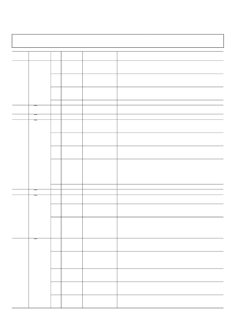
AD9984A
Hex
Address
Rev. 0 | Page 26 of 44
Read/Write,
Read Only
Bits
3
Default
Value
**** 0***
Register Name
Description
Red Clamp Select.
0 = Clamp the red channel to ground.
1 = Clamp the red channel to midscale.
Green Clamp Select.
0 = Clamp the green channel to ground.
1 = Clamp the green channel to midscale.
Blue Clamp Select.
0 = Clamp the blue channel to ground.
1 = Clamp the blue channel to midscale.
Must be set to 0 for proper operation.
Places the clamp signal an integer number of clock periods after the
trailing edge of the Hsync signal.
Number of clock periods that the clamp signal is actively clamping.
Clamp Polarity Override.
0 = The chip selects the clamp polarity.
1 = The polarity of the clamp signal is set by Reg. 0x1B, Bit 6.
Clamp Polarity. This bit is used only if Reg. 0x1B, Bit 7 is set to 1.
0 = Clamp polarity is negative.
1 = Clamp polarity is positive.
Auto-Offset Enable.
0 = Auto-offset is disabled.
1 = Auto-offset is enabled (offsets become the desired clamp code).
Auto-Offset Update Frequency. This selects how often the auto-
offset circuit operates.
00 = Every 3 clamps.
01 = Every 48 clamps.
10 = Every 192 clamps.
11 = Every 3 Vsync periods.
Must be written to default (011) for proper operation.
Must be set to 0xFF for proper operation.
SOG Slicer Comparator Threshold. Sets the voltage level of SOG slicer’s
comparator.
SOGOUT Polarity. Sets the polarity of the signal on the SOGOUT pin.
0 = SOGOUT polarity is negative.
1 = SOGOUT polarity is positive.
SOGOUT Select.
00 = Raw SOGINx.
01 = Raw HSYNCx.
10 = Regenerated Hsync from sync filter.
11 = Filtered Hsync from sync filter.
Channel Select Override.
0 = The chip determines which input channels to use.
1 = The input channel selection is determined by Reg. 0x1E, Bit 6.
Channel Select. This is used only if Reg. 0x1E, Bit 7 is set to 1, or if
syncs are present on both channels.
0 = Channel 0 syncs and data are selected.
1 = Channel 1 syncs and data are selected.
Programmable Bandwidth.
0 = Low analog input bandwidth (~7 MHz).
1 = High analog input bandwidth (~300 MHz).
Power-Down Control Select.
0 = Manual power-down control.
1 = Auto power-down control.
Power-Down.
0 = Normal operation.
1 = Power-down.
2
**** *0**
1
**** **0*
0x19
R/W
0
7:0
**** ***0
0000 1000
Clamp Placement
0x1A
0x1B
R/W
R/W
7:0
7
0010 0000
0*** ****
Clamp Duration
Clamp and Offset
6
*1** ****
5
**0* ****
4:3
***1 1***
0x1C
0x1D
R/W
R/W
2:0
7:0
7:3
**** *011
1111 1111
0111 1***
Test Register 0
SOG Control
2
**** *0**
1:0
**** **00
0x1E
R/W
7
*** ****
Input and Power
Control
6
*0** ****
5
**1* ****
4
***1 ****
3
**** 0***
相關(guān)PDF資料 |
PDF描述 |
|---|---|
| AD9985A | 110 MSPS/140 MSPS Analog Interface for Flat Panel Displays |
| AD9985ABSTZ-110 | 110 MSPS/140 MSPS Analog Interface for Flat Panel Displays |
| AD9985AKSTZ-110 | 110 MSPS/140 MSPS Analog Interface for Flat Panel Displays |
| AD9985AKSTZ-140 | 110 MSPS/140 MSPS Analog Interface for Flat Panel Displays |
| AD9985BSTZ-110 | 110 MSPS/140 MSPS Analog Interface for Flat Panel Displays |
相關(guān)代理商/技術(shù)參數(shù) |
參數(shù)描述 |
|---|---|
| AD9984KSTZ-110 | 制造商:Rochester Electronics LLC 功能描述: 制造商:Analog Devices 功能描述: |
| AD9984KSTZ-140 | 制造商:Rochester Electronics LLC 功能描述: 制造商:Analog Devices 功能描述: |
| AD9984KSTZ-170 | 制造商:Analog Devices 功能描述: |
| AD9985 | 制造商:AD 制造商全稱:Analog Devices 功能描述:110 MSPS/140 MSPS Analog Interface for Flat Panel Displays |
| AD9985/PCB | 制造商:AD 制造商全稱:Analog Devices 功能描述:110 MSPS/140 MSPS Analog Interface for Flat Panel Displays |
發(fā)布緊急采購,3分鐘左右您將得到回復(fù)。