- 您現(xiàn)在的位置:買賣IC網(wǎng) > PDF目錄373972 > AD9984APCBZ (Analog Devices, Inc.) High Performance 10-Bit Display Interface PDF資料下載
參數(shù)資料
| 型號: | AD9984APCBZ |
| 廠商: | Analog Devices, Inc. |
| 英文描述: | High Performance 10-Bit Display Interface |
| 中文描述: | 高性能10位顯示接口 |
| 文件頁數(shù): | 21/44頁 |
| 文件大小: | 490K |
| 代理商: | AD9984APCBZ |
第1頁第2頁第3頁第4頁第5頁第6頁第7頁第8頁第9頁第10頁第11頁第12頁第13頁第14頁第15頁第16頁第17頁第18頁第19頁第20頁當前第21頁第22頁第23頁第24頁第25頁第26頁第27頁第28頁第29頁第30頁第31頁第32頁第33頁第34頁第35頁第36頁第37頁第38頁第39頁第40頁第41頁第42頁第43頁第44頁
AD9984A
COAST TIMING
In most computer systems, the Hsync signal is provided
continuously on a dedicated wire. In these systems, the COAST
input and function are unnecessary and should not be used.
In some systems, however, Hsync is disturbed during the
vertical sync period (Vsync). In some cases, Hsync pulses
disappear. In other systems, such as those that employ
composite sync (Csync) signals or embedded sync-on-green,
Hsync can include equalization pulses or other distortions
during Vsync. To avoid upsetting the clock generator during
Vsync, it is important to ignore these distortions. If the pixel
clock PLL sees extraneous pulses, it attempts to lock to this new
frequency, and changes frequency by the end of the Vsync
period. It then takes a few lines of correct Hsync timing to
recover at the beginning of a new frame, resulting in a tearing of
the image at the top of the display.
The COAST input is provided to eliminate this problem. It is an
asynchronous input that disables the PLL input and holds the
clock at its current frequency. The PLL can free run for several
lines without significant frequency drift. Coast can be generated
internally by the AD9984A (see Register 0x18) or can be
provided externally by the graphics controller.
When internal coast is selected (Register 0x18, Bit 7 = 0, and
Register 0x14, Bits[7:6] to select source), Vsync is used as a basis for
determining the position of coast. The internal coast signal is
enabled a programmed number of Hsync periods before the
periodic Vsync signal (Precoast Register 0x16), and it is
dropped a programmed number of Hsync periods after Vsync
(Postcoast Register 0x17). It is recommended that the Vsync
filter be enabled when using the internal coast function to allow
the AD9984A to precisely determine the number of Hsyncs/Vsync
and their location. In many applications where disruptions
occur and coast is used, values of 2 for precoast and 10d for
postcoast are sufficient to avoid most extraneous pulses.
Rev. 0 | Page 21 of 44
OUTPUT FORMATTER
The output formatter is capable of generating several output
formats to be presented to the 30 data output pins. The output
formats and the pin assignments for each format are listed in
Table 12. In addition, there are several clock options for the
output clock. The user can select the pixel clock, a 90° phase-
shifted pixel clock, a 2× pixel clock, or a 0.5× pixel clock for test
purposes. The output clock can also be inverted.
Data output is available as 30-pin RGB or YCbCr, or, if either
4:2:2 or 4:4:4 DDR is selected, a secondary channel is available.
This secondary channel is always 4:2:2 DDR. It contains the
same video data as the primary channel and can be utilized by
either another display or storage device. Depending on the
choice of output modes, the primary output can be 30 pins,
20 pins, or as few as 15 pins.
Mode Descriptions
4:4:4
All channels come out with their 10 data bits at the same time.
Data is aligned to the negative edge of the clock for easy capture.
This is the normal 30-bit output mode for RGB or 4:4:4 YCbCr.
4:2:2
Red and green channels contain 4:2:2 formatted data (20 pins)
with Y data on the green channel and Cb, Cr data on the red
channel. Data is aligned to the negative edge of the clock. The
blue channel contains the secondary channel with Cb, Y, Cr, Y
formatted 4:2:2 DDR data. The data edges are aligned to both
edges of the pixel clock, therefore, using a 90° clock may be
necessary to capture the DDR data.
4:4:4 DDR
This mode puts out full 4:4:4 data on 15 bits of the red and
green channels, thus saving 15 pins. The first half (RGB[14:0])
of the 30-bit data is sent on the rising edge and the second half
(RGB[29:15]) is sent on the falling edge. DDR 4:2:2 data is sent
on the blue channel, as in 4:2:2 mode.
RGB[29:0] = R[9:0] + G[9:0] + B[9:0], so
RGB[29:15] = R[9:0] + G[9:5] and
RGB[14:0] = G[4:0] + B[9:0]
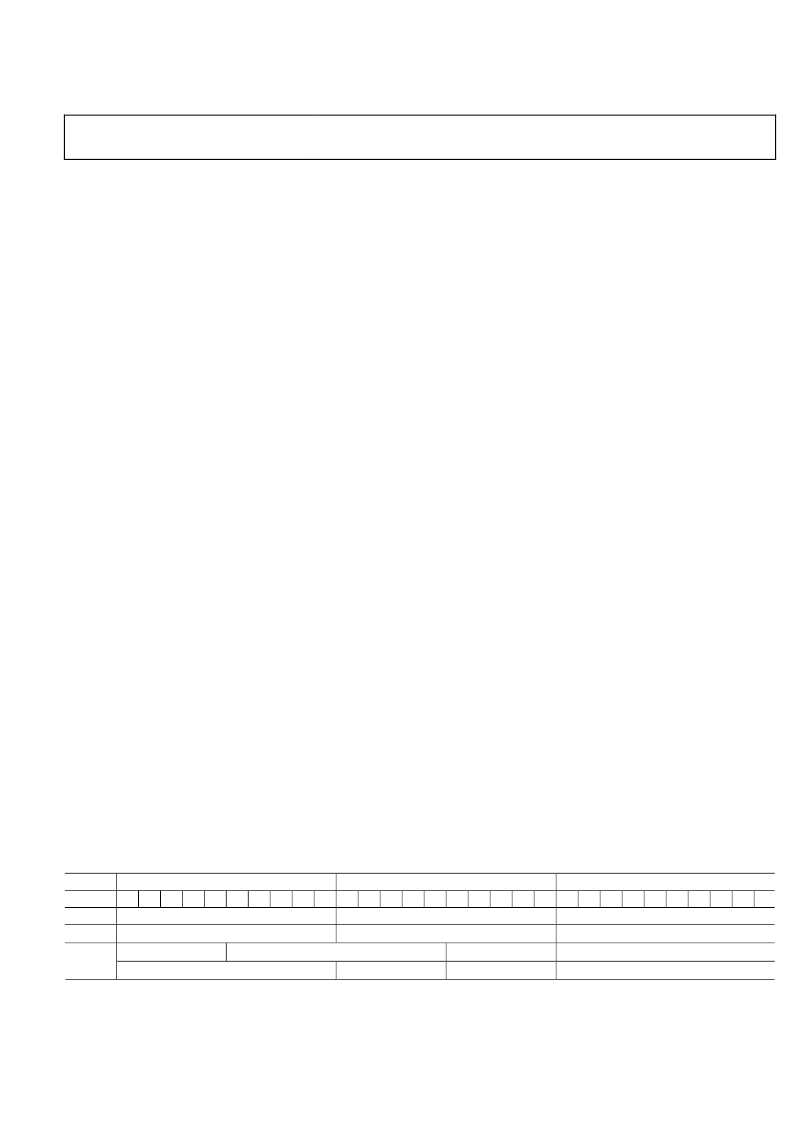
Table 12. Output Formats
1
Port
Bit
9
4:4:4
4:2:2
2
DDR
↑
G[4:0]
4:4:4
DDR
Red
5
Red/Cr
Cb, Cr
Green
5
Green/Y
Y
Blue
5
Blue/Cb
8
7
6
4
3
2
1
0
9
8
7
6
4
3
2
1
0
9
8
7
6
4
3
2
1
0
DDR 4:2:2
↑
Cb,Cr
↓
Y,Y
DDR 4:2:2
↑
Cb,Cr
DDR 4:2:2
↓
Y,Y
DDR
↑
B[9:0]
N/A
N/A
DDR
↓
R[9:0]
DDR
↓
G[9:5]
1
Arrows in table indicate clock edge. Rising edge of clock =
↑
, falling edge =
↓
.
2
For 4:2:2 modes, Cb is sent before Cr.
相關(guān)PDF資料 |
PDF描述 |
|---|---|
| AD9985A | 110 MSPS/140 MSPS Analog Interface for Flat Panel Displays |
| AD9985ABSTZ-110 | 110 MSPS/140 MSPS Analog Interface for Flat Panel Displays |
| AD9985AKSTZ-110 | 110 MSPS/140 MSPS Analog Interface for Flat Panel Displays |
| AD9985AKSTZ-140 | 110 MSPS/140 MSPS Analog Interface for Flat Panel Displays |
| AD9985BSTZ-110 | 110 MSPS/140 MSPS Analog Interface for Flat Panel Displays |
相關(guān)代理商/技術(shù)參數(shù) |
參數(shù)描述 |
|---|---|
| AD9984KSTZ-110 | 制造商:Rochester Electronics LLC 功能描述: 制造商:Analog Devices 功能描述: |
| AD9984KSTZ-140 | 制造商:Rochester Electronics LLC 功能描述: 制造商:Analog Devices 功能描述: |
| AD9984KSTZ-170 | 制造商:Analog Devices 功能描述: |
| AD9985 | 制造商:AD 制造商全稱:Analog Devices 功能描述:110 MSPS/140 MSPS Analog Interface for Flat Panel Displays |
| AD9985/PCB | 制造商:AD 制造商全稱:Analog Devices 功能描述:110 MSPS/140 MSPS Analog Interface for Flat Panel Displays |
發(fā)布緊急采購,3分鐘左右您將得到回復(fù)。