- 您現在的位置:買賣IC網 > PDF目錄16827 > XR17V354IB-0A-EVB (Exar Corporation)EVAL BOARD FOR XR17V354-A 176BGA PDF資料下載
參數資料
| 型號: | XR17V354IB-0A-EVB |
| 廠商: | Exar Corporation |
| 文件頁數: | 11/66頁 |
| 文件大?。?/td> | 0K |
| 描述: | EVAL BOARD FOR XR17V354-A 176BGA |
| 產品培訓模塊: | PCIe UARTs |
| 標準包裝: | 1 |
| 主要目的: | 接口,UART |
| 嵌入式: | 否 |
| 已用 IC / 零件: | XR17V354 |
| 已供物品: | 板 |
| 其它名稱: | 1016-1611 XR17V354IB-0A-EVB-ND |
第1頁第2頁第3頁第4頁第5頁第6頁第7頁第8頁第9頁第10頁當前第11頁第12頁第13頁第14頁第15頁第16頁第17頁第18頁第19頁第20頁第21頁第22頁第23頁第24頁第25頁第26頁第27頁第28頁第29頁第30頁第31頁第32頁第33頁第34頁第35頁第36頁第37頁第38頁第39頁第40頁第41頁第42頁第43頁第44頁第45頁第46頁第47頁第48頁第49頁第50頁第51頁第52頁第53頁第54頁第55頁第56頁第57頁第58頁第59頁第60頁第61頁第62頁第63頁第64頁第65頁第66頁
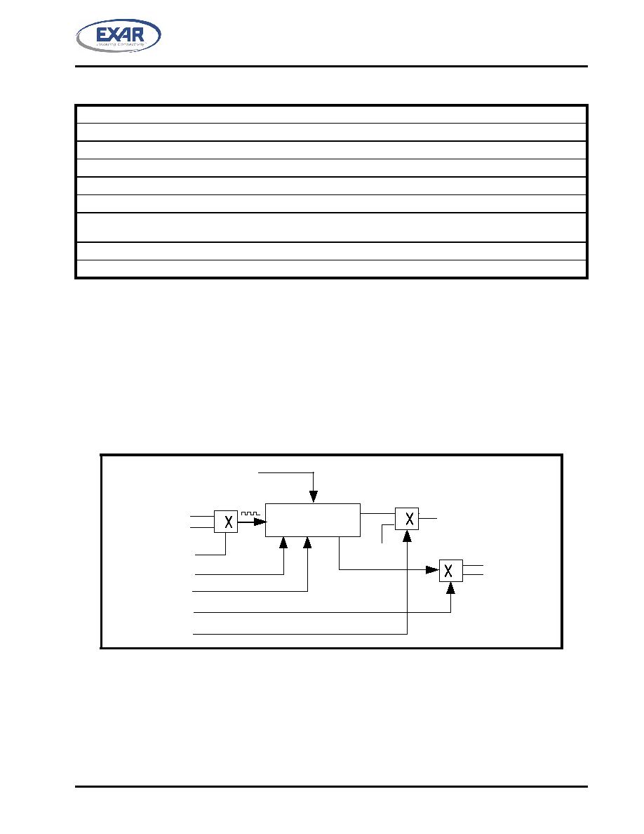
TABLE 8: UART CHANNEL [3:0] INTERRUPT CLEARING
Wake-up Indicator is cleared by reading the INT0 register.
RXRDY and RXRDY Time-out is cleared by reading data in the RX FIFO.
RX Line Status interrupt clears after reading the LSR register that is in the UART channel register set.
TXRDY interrupt clears after reading ISR register that is in the UART channel register set.
Modem Status Register interrupt clears after reading MSR register that is in the UART channel register set.
RTS/CTS or DTR/DSR delta interrupt clears after reading MSR register that is in the UART channel register set.
Xoff/Xon delta and special character detect interrupt clears after reading the ISR register that is in the UART channel reg-
ister set.
TIMER Time-out interrupt clears after reading the TIMERCNTL register that is in the Device Configuration register set.
MPIO interrupt clears after reading the MPIOLVL register that is in the Device Configuration register set.
XR17V354
19
REV. 1.0.3
HIGH PERFORMANCE QUAD PCI-EXPRESS UART
1.4.2
General Purpose 16-bit Timer/Counter [TIMERMSB, TIMELSB, TIMER, TIMECNTL] (DEFAULT
0XXX-XX-00-00)
The XR17V354 has a general purpose 16-bit timer/counter. The internal 125MHz clock (master mode) or
62.5MHz clock (slave mode) or the external clock at the TMRCK input pin can be selected as the clock source
for the timer/counter. The timer can be set to be a single-shot for a one-time event or re-triggerable for a
periodic signal. An interrupt may be generated when the timer times out and will show up as a Channel 0
interrupt (see Table 7). It is controlled through 4 configuration registers [TIMERCNTL, TIMER, TIMELSB,
TIMERMSB]. The TIMERCNTL register provides the Timer commands such as start/stop, as shown in Table 9
below. The time-out output of the Timer can also be optionally routed to the MPIO[0] pin. The block diagram of
the Timer/Counter circuit is shown below:
FIGURE 5. TIMER/COUNTER CIRCUIT
Timer Interrupt
Timer
Output
MPIOLVL[0]
0
1
0
1
Timer Interrupt
No Interrupt
MPIO[0]
TMRCK
125MHz/62.5MHz
TIMERCNTL
COMMANDS
16-Bit
Timer/Counter
Start/Stop
Timer Interrupt Enable/ Disable
Single shot/Re-triggerable
TIMERMSB and TIMERLSB
(16-bit Value)
0
1
Clock Select
Route/De-route to MPIO[0]
TIMERMSB [31:24] and TIMERLSB [23:16] registers
The concatentaion of the 8-bit registers TIMERMSB and TIMERLSB forms a 16-bit value which decides the
time-out period of the Timer, per the following equation:
Timer output frequency = Timer input clock / 16-bit Timer value
The least-significant bit of the timer is being bit [0] of the TIMERLSB with most-significant-bit being bit [7] in
TIMERMSB. Notice that these registers do not hold the current counter value when read. Default value is zero
(timer disabled) upon powerup and reset. The ’Reset Timer’ command does not have any effect on this
register.
相關PDF資料 |
PDF描述 |
|---|---|
| 202A196-3-0 | BOOT MOLDED |
| 570-002-734-100 | ASSEMBLY PLUG 2POS WATERPROOF |
| LMR040-0700-CCF9-2KIT4X | KIT DEV LMR040-0700, 230V |
| 322A024-25-0 | BOOT MOLDED |
| 0210490393 | CABLE JUMPER 1.25MM .102M 32POS |
相關代理商/技術參數 |
參數描述 |
|---|---|
| XR17V354IB176-F | 功能描述:UART 接口集成電路 4 Channel PCIe UART w/256 Byte FIFO RoHS:否 制造商:Texas Instruments 通道數量:2 數據速率:3 Mbps 電源電壓-最大:3.6 V 電源電壓-最小:2.7 V 電源電流:20 mA 最大工作溫度:+ 85 C 最小工作溫度:- 40 C 封裝 / 箱體:LQFP-48 封裝:Reel |
| XR17V354IB-E4-EVB | 功能描述:界面開發(fā)工具 Eval Board for XR17V354IB-E4 RoHS:否 制造商:Bourns 產品:Evaluation Boards 類型:RS-485 工具用于評估:ADM3485E 接口類型:RS-485 工作電源電壓:3.3 V |
| XR17V354IB-E8-EVB | 功能描述:界面開發(fā)工具 Eval Board for XR17V354IB-E8 RoHS:否 制造商:Bourns 產品:Evaluation Boards 類型:RS-485 工具用于評估:ADM3485E 接口類型:RS-485 工作電源電壓:3.3 V |
| XR17V358 | 制造商:EXAR 制造商全稱:EXAR 功能描述:HIGH PERFORMANCE OCTAL PCI EXPRESS UART |
| XR17V358IB-0A-EVB | 功能描述:界面開發(fā)工具 Eval Board for XR17V358IB-0A RoHS:否 制造商:Bourns 產品:Evaluation Boards 類型:RS-485 工具用于評估:ADM3485E 接口類型:RS-485 工作電源電壓:3.3 V |
發(fā)布緊急采購,3分鐘左右您將得到回復。