- 您現(xiàn)在的位置:買賣IC網(wǎng) > PDF目錄359412 > VPX3224D (Electronic Theatre Controls, Inc.) Video Pixel Decoders PDF資料下載
參數(shù)資料
| 型號(hào): | VPX3224D |
| 廠商: | Electronic Theatre Controls, Inc. |
| 英文描述: | Video Pixel Decoders |
| 中文描述: | 視頻解碼器像素 |
| 文件頁數(shù): | 13/92頁 |
| 文件大小: | 672K |
| 代理商: | VPX3224D |
第1頁第2頁第3頁第4頁第5頁第6頁第7頁第8頁第9頁第10頁第11頁第12頁當(dāng)前第13頁第14頁第15頁第16頁第17頁第18頁第19頁第20頁第21頁第22頁第23頁第24頁第25頁第26頁第27頁第28頁第29頁第30頁第31頁第32頁第33頁第34頁第35頁第36頁第37頁第38頁第39頁第40頁第41頁第42頁第43頁第44頁第45頁第46頁第47頁第48頁第49頁第50頁第51頁第52頁第53頁第54頁第55頁第56頁第57頁第58頁第59頁第60頁第61頁第62頁第63頁第64頁第65頁第66頁第67頁第68頁第69頁第70頁第71頁第72頁第73頁第74頁第75頁第76頁第77頁第78頁第79頁第80頁第81頁第82頁第83頁第84頁第85頁第86頁第87頁第88頁第89頁第90頁第91頁第92頁
VPX 3225D, VPX 3224D
PRELIMINARY DATA SHEET
13
Micronas
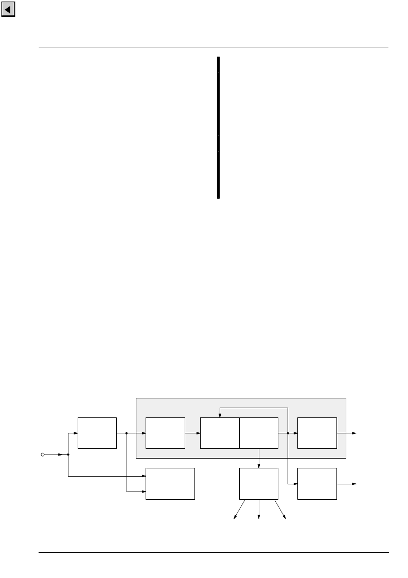
2.3. Video Sync Processing
Fig. 2–10 shows a block diagram of the front-end sync
processing. To extract the sync information from the
video signal, a linear phase lowpass filter eliminates all
noise and video contents above 1 MHz. The sync is sep-
arated by a slicer; the sync phase is measured. The in-
ternal controller can select variable windows to improve
the noise immunity of the slicer. The phase comparator
measures the falling edge of sync, as well as the inte-
grated sync pulse.
The sync phase error is filtered by a phase-locked loop
that is computed by the FP. All timing in the front-end is
derived from a counter that is part of this PLL, and it thus
counts synchronously to the video signal.
A separate hardware block measures the signal back
porch and also allows gathering the maximum/minimum
of the video signal. This information is processed by the
FP and used for gain control and clamping.
For vertical sync separation, the sliced video signal is in-
tegrated. The FP uses the integrator value to derive ver-
tical sync and field information.
Frequency and phase characteristics of the analog vid-
eo signal are derived from PLL1. The results are fed to
the rest of the video processing system in the backend.
The resizer unit uses them for data interpolation and
orthogonalization. A separate timing block derives the
timing reference signals HREF and VREF from the hori-
zontal sync.
2.4. Macrovision Detection (version D4 only)
Video signals from Macrovision encoded VCR tapes are
decoded without loss of picture quality. However, it might
be necessary in some applications to detect the pres-
ence of Macrovision encoded video signals. This is pos-
sible by reading a set of I
2
C registers (FP-RAM
0x170–0x179) in the video front-end.
Macrovision encoded video signals typically have AGC
pulses and pseudo sync pulses added during VBI. The
amplitude of the AGC pulses is modulated in time. The
Macrovision detection logic measures the VBI lines and
compares the signal against programmable thresholds.
The window in which the video lines are checked for Ma-
crovision pulses can be defined in terms of start and stop
line (e.g. 6–15 for NTSC).
Fig. 2–10:
Sync separation block diagram
lowpass
1 MHz &
sync
slicer
horizontal
sync
separation
clamp &
signal
measurement
phase
comparator
& lowpass
counter
front-end
timing
front
sync
generator
clock
synthesizer
syncs
front sync
skew
vblank
field
clock
H/V syncs
clamping
video
input
color key
FIFO_write
PLL1
相關(guān)PDF資料 |
PDF描述 |
|---|---|
| VPX3224E | Video Pixel Decoders |
| VPX322XE | Video Pixel Decoders |
| VQ1000J | N-Channel Enhancement-Mode MOSFET Transistor(最小漏源擊穿電壓60V,夾斷電流0.225A的N溝道增強(qiáng)型MOSFET晶體管) |
| VQ1000J | N-Channel 60-V (D-S) MOSFET |
| VQ1001J | Dual N-Channel 30-V (D-S) MOSFET with Schottky Diode |
相關(guān)代理商/技術(shù)參數(shù) |
參數(shù)描述 |
|---|---|
| VPX3224D-C3 | 制造商:未知廠家 制造商全稱:未知廠家 功能描述:Microprocessor |
| VPX3224E | 制造商:MICRONAS 制造商全稱:MICRONAS 功能描述:Video Pixel Decoders |
| VPX3225D | 制造商:未知廠家 制造商全稱:未知廠家 功能描述:Video Pixel Decoders |
| VPX3225D-C3 | 制造商:未知廠家 制造商全稱:未知廠家 功能描述:Microprocessor |
| VPX3225E | 制造商:MICRONAS 制造商全稱:MICRONAS 功能描述:Video Pixel Decoders |
發(fā)布緊急采購,3分鐘左右您將得到回復(fù)。