- 您現(xiàn)在的位置:買賣IC網(wǎng) > PDF目錄383983 > UPD77111GK (NEC Corp.) 16-BIT FIXED-POINT DIGITAL SIGNAL PROCESSORS PDF資料下載
參數(shù)資料
| 型號: | UPD77111GK |
| 廠商: | NEC Corp. |
| 元件分類: | 數(shù)字信號處理 |
| 英文描述: | 16-BIT FIXED-POINT DIGITAL SIGNAL PROCESSORS |
| 中文描述: | 16位定點(diǎn)數(shù)字信號處理器 |
| 文件頁數(shù): | 24/80頁 |
| 文件大小: | 451K |
| 代理商: | UPD77111GK |
第1頁第2頁第3頁第4頁第5頁第6頁第7頁第8頁第9頁第10頁第11頁第12頁第13頁第14頁第15頁第16頁第17頁第18頁第19頁第20頁第21頁第22頁第23頁當(dāng)前第24頁第25頁第26頁第27頁第28頁第29頁第30頁第31頁第32頁第33頁第34頁第35頁第36頁第37頁第38頁第39頁第40頁第41頁第42頁第43頁第44頁第45頁第46頁第47頁第48頁第49頁第50頁第51頁第52頁第53頁第54頁第55頁第56頁第57頁第58頁第59頁第60頁第61頁第62頁第63頁第64頁第65頁第66頁第67頁第68頁第69頁第70頁第71頁第72頁第73頁第74頁第75頁第76頁第77頁第78頁第79頁第80頁
Data Sheet U12801EJ4V0DS00
24
μ
PD77110, 77111, 77112
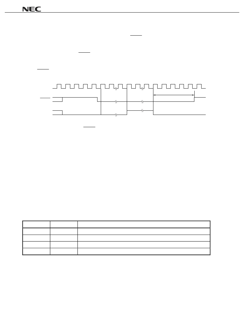
4.2 Initializing PLL
Initializing the PLL starts from the 1024th input clock after the RESET pin has been asserted active (low level).
Initialization takes 1024 clocks and it takes the PLL 100
μ
s to be locked.
After that, the DSP operates with the set value of the PLL specified by a mask option (
μ
PD77111 or 77112) or an
external pin (
μ
PD77110) when the RESET pin is deasserted inactive (high level).
After initializing the PLL, be sure to execute boot-up processing to re-initialize the internal RAM. To initialize the
PLL, the internal memory contents and register status of the DSP are not retained.
If the RESET pin is deasserted inactive before the PLL initialization mode is set, the DSP is normally reset (the
PLL is not initialized).
CLKIN
RESET
PLL initialization
mode
1024
1
2048
PLL lock time
Approx. 100 s
PLL initialization
(internal status)
Caution Do not deassert the RESET signal inactive in the PLL initialization mode and during PLL lock
period.
5. FUNCTIONS OF BOOT-UP ROM
To rewrite the contents of the instruction memory on power application or from program, boot up the instruction
RAM by using the internal boot-up ROM.
The
μ
PD77110 has a function to verify the contents of the internal instruction RAM in the boot-up ROM.
5.1 Boot at Reset
After hardware reset has been cleared, the boot program first reads the general-purpose I/O ports P0 and P1 and,
depending on their bit pattern, determines the boot mode (self boot or host boot). After boot processing, processing
is executed starting from the instruction at address 0x200 (reset entry) of the instruction memory.
The pins (P0 and P1) that specify the boot mode must be kept stable for the duration of 3 clocks before and for
the duration of 12 clocks after reset has been cleared (the clock is input from CLKIN).
P1
P0
Boot Mode
0
0
Does not execute boot but branches to address 0x200
Note
.
0
1
Executes host boot and then branches to address 0x200.
1
1
Executes self boot and then branches to address 0x200.
1
0
Setting prohibited
Note
This setting is used when the DSP must be reset to recover from the standby mode after reset boot has
been executed once.
相關(guān)PDF資料 |
PDF描述 |
|---|---|
| UPD77110 | 16-BIT FIXED-POINT DIGITAL SIGNAL PROCESSORS |
| UPD77111 | 16-BIT FIXED-POINT DIGITAL SIGNAL PROCESSORS |
| UPD77112 | 16-BIT FIXED-POINT DIGITAL SIGNAL PROCESSORS |
| UPD77112GC | 16-BIT FIXED-POINT DIGITAL SIGNAL PROCESSORS |
| UPD780016Y | 8-bit Microcontroller with 2/4/8K Bytes In-System Programmable Flash |
相關(guān)代理商/技術(shù)參數(shù) |
參數(shù)描述 |
|---|---|
| UPD7759C | 制造商: 功能描述: 制造商:undefined 功能描述: 制造商:Panasonic Industrial Company 功能描述:IC |
| UPD780023AGB-G43-8EU-X3-A | 制造商:Renesas Electronics Corporation 功能描述: |
| UPD780023AGB-G44-8EU-E3-A | 制造商:Renesas Electronics Corporation 功能描述: |
| UPD780023AGC-107-8BS-A | 制造商:Renesas Electronics Corporation 功能描述:NECUPD780023AGC-107-8BS-A MASK ROM DEVIC |
| UPD780023AGK-C74-9ET-A | 制造商:Renesas Electronics Corporation 功能描述: |
發(fā)布緊急采購,3分鐘左右您將得到回復(fù)。