- 您現(xiàn)在的位置:買賣IC網(wǎng) > PDF目錄98307 > TWL1110GQE (TEXAS INSTRUMENTS INC) SPECIALTY CONSUMER CIRCUIT, PBGA80 PDF資料下載
參數(shù)資料
| 型號: | TWL1110GQE |
| 廠商: | TEXAS INSTRUMENTS INC |
| 元件分類: | 消費(fèi)家電 |
| 英文描述: | SPECIALTY CONSUMER CIRCUIT, PBGA80 |
| 封裝: | PLASTIC, MICRO, BGA-80 |
| 文件頁數(shù): | 13/37頁 |
| 文件大小: | 496K |
| 代理商: | TWL1110GQE |
第1頁第2頁第3頁第4頁第5頁第6頁第7頁第8頁第9頁第10頁第11頁第12頁當(dāng)前第13頁第14頁第15頁第16頁第17頁第18頁第19頁第20頁第21頁第22頁第23頁第24頁第25頁第26頁第27頁第28頁第29頁第30頁第31頁第32頁第33頁第34頁第35頁第36頁第37頁

TWL1110
VOICE-BAND AUDIO PROCESSOR (VBAP
)
SLWS103 – NOVEMBER 2000
20
POST OFFICE BOX 655303
DALLAS, TEXAS 75265
PRINCIPLES OF OPERATION
power-on initialization
An external reset with a minimum pulse width of 500 ns must be applied to the active low RESET terminal to
guarantee reset upon power on. All registers are set with default values upon external reset initialization.
The desired selection for all programmable functions can be initialized prior to a power-up command using the
control interface.
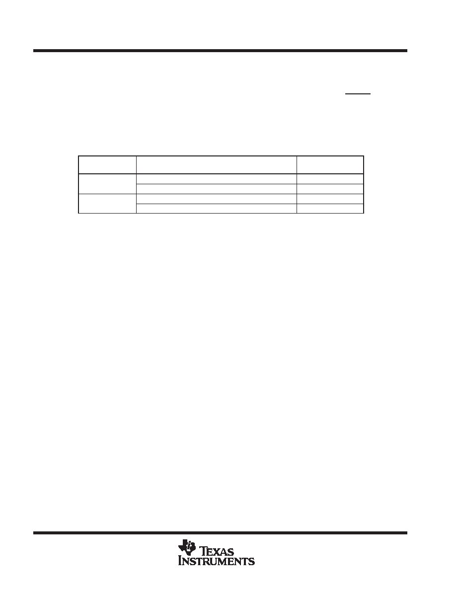
Table 1. Power Up and Power Down Procedures (VDD = 2.7 V, earphone amplifier unloaded)
DEVICE STATUS
PROCEDURE
MAXIMUM POWER
CONSUMPTION
Power up
Set bit 1 = 1 in power control register, EAR1 enabled
16.2 mW
Power up
Set bit 1 = 0 in power control register, EAR2 enabled
14.6 mW
Power down
Set bit 7 = 1 in TXPGA control register and bit 0 = 0
1.35
W
Power down
Set bit 7 = 0 in TXPGA control register and bit 0 = 0
67.5
W
In addition to resetting the power down bit in the power control register, loss of MCLK (no transition detected)
automatically enters the device into a power down state with PCMO in the high impedance state. If during a pulse
code modulation (PCM) data transmit cycle an asynchronous power down occurs, the PCM interface remains
powered up until the PCM data is completely transferred.
An additional power down mode overrides the MCLK detection function. This allows the device to enter the
power down state without regard to MCLK. Setting bit 7 of the TXPGA sidetone register to logic high enables
this function.
internal reference current setting terminal
Use a 100-k
precision resistor to connect the REXT pin to GND.
conversion laws
The device can be programmed for either a 15-bit linear or and 8-bit
(-law or A-law) companding mode. The
companding operation approximates the CCITT G.711 recommendation. The linear mode operation uses a
15-bit twos-complement format.
transmit operation
microphone input
The microphone input stage is a low-noise differential amplifier that provides a preamplifier gain of 23.5 dB. It
is recommended that a microphone capacitively connected to the MIC1N and MIC1P inputs, while the MIC2N
and MIC2P inputs can be used to capacitively connect a second microphone or an auxiliary audio circuit.
相關(guān)PDF資料 |
PDF描述 |
|---|---|
| TWL1110PBSR | SPECIALTY CONSUMER CIRCUIT, PQFP32 |
| TWL1110GQER | SPECIALTY CONSUMER CIRCUIT, PBGA80 |
| TWL1110PBS | SPECIALTY CONSUMER CIRCUIT, PQFP32 |
| TWL2213CAPFBR | 1-CHANNEL POWER SUPPLY SUPPORT CKT, PQFP48 |
| TWL2214CAGQER | 1-CHANNEL POWER SUPPLY SUPPORT CKT, PBGA48 |
相關(guān)代理商/技術(shù)參數(shù) |
參數(shù)描述 |
|---|---|
| TWL1110GQER | 制造商:Texas Instruments 功能描述:VOICE BAND AUD PROCESSOR 80BGA MICROSTAR JUNIOR - Tape and Reel |
| TWL1110PBS | 制造商:Rochester Electronics LLC 功能描述:- Bulk |
| TWL1110PBSR | 制造商:Rochester Electronics LLC 功能描述:- Bulk |
| TWL1110TQFP | 制造商:TI 制造商全稱:Texas Instruments 功能描述:VOICE-BAND AUDIO PROCESSOR VBAPE |
| TWL1200 | 制造商:TI 制造商全稱:Texas Instruments 功能描述:SDIO, UART, AND AUDIO VOLTAGE-TRANSLATION TRANSCEIVER |
發(fā)布緊急采購,3分鐘左右您將得到回復(fù)。