- 您現(xiàn)在的位置:買(mǎi)賣(mài)IC網(wǎng) > PDF目錄199412 > TMP86CH09NG 8-BIT, MROM, 16 MHz, MICROCONTROLLER, PDIP32 PDF資料下載
參數(shù)資料
| 型號(hào): | TMP86CH09NG |
| 元件分類(lèi): | 微控制器/微處理器 |
| 英文描述: | 8-BIT, MROM, 16 MHz, MICROCONTROLLER, PDIP32 |
| 封裝: | 0.400 INCH, 1.78 MM PITCH, LEAD FREE, PLASTIC, SDIP-32 |
| 文件頁(yè)數(shù): | 4/120頁(yè) |
| 文件大?。?/td> | 1743K |
| 代理商: | TMP86CH09NG |
第1頁(yè)第2頁(yè)第3頁(yè)當(dāng)前第4頁(yè)第5頁(yè)第6頁(yè)第7頁(yè)第8頁(yè)第9頁(yè)第10頁(yè)第11頁(yè)第12頁(yè)第13頁(yè)第14頁(yè)第15頁(yè)第16頁(yè)第17頁(yè)第18頁(yè)第19頁(yè)第20頁(yè)第21頁(yè)第22頁(yè)第23頁(yè)第24頁(yè)第25頁(yè)第26頁(yè)第27頁(yè)第28頁(yè)第29頁(yè)第30頁(yè)第31頁(yè)第32頁(yè)第33頁(yè)第34頁(yè)第35頁(yè)第36頁(yè)第37頁(yè)第38頁(yè)第39頁(yè)第40頁(yè)第41頁(yè)第42頁(yè)第43頁(yè)第44頁(yè)第45頁(yè)第46頁(yè)第47頁(yè)第48頁(yè)第49頁(yè)第50頁(yè)第51頁(yè)第52頁(yè)第53頁(yè)第54頁(yè)第55頁(yè)第56頁(yè)第57頁(yè)第58頁(yè)第59頁(yè)第60頁(yè)第61頁(yè)第62頁(yè)第63頁(yè)第64頁(yè)第65頁(yè)第66頁(yè)第67頁(yè)第68頁(yè)第69頁(yè)第70頁(yè)第71頁(yè)第72頁(yè)第73頁(yè)第74頁(yè)第75頁(yè)第76頁(yè)第77頁(yè)第78頁(yè)第79頁(yè)第80頁(yè)第81頁(yè)第82頁(yè)第83頁(yè)第84頁(yè)第85頁(yè)第86頁(yè)第87頁(yè)第88頁(yè)第89頁(yè)第90頁(yè)第91頁(yè)第92頁(yè)第93頁(yè)第94頁(yè)第95頁(yè)第96頁(yè)第97頁(yè)第98頁(yè)第99頁(yè)第100頁(yè)第101頁(yè)第102頁(yè)第103頁(yè)第104頁(yè)第105頁(yè)第106頁(yè)第107頁(yè)第108頁(yè)第109頁(yè)第110頁(yè)第111頁(yè)第112頁(yè)第113頁(yè)第114頁(yè)第115頁(yè)第116頁(yè)第117頁(yè)第118頁(yè)第119頁(yè)第120頁(yè)
Page 90
9. 8-Bit TimerCounter (TC3, TC4)
9.1 Configuration
TMP86FH09ANG
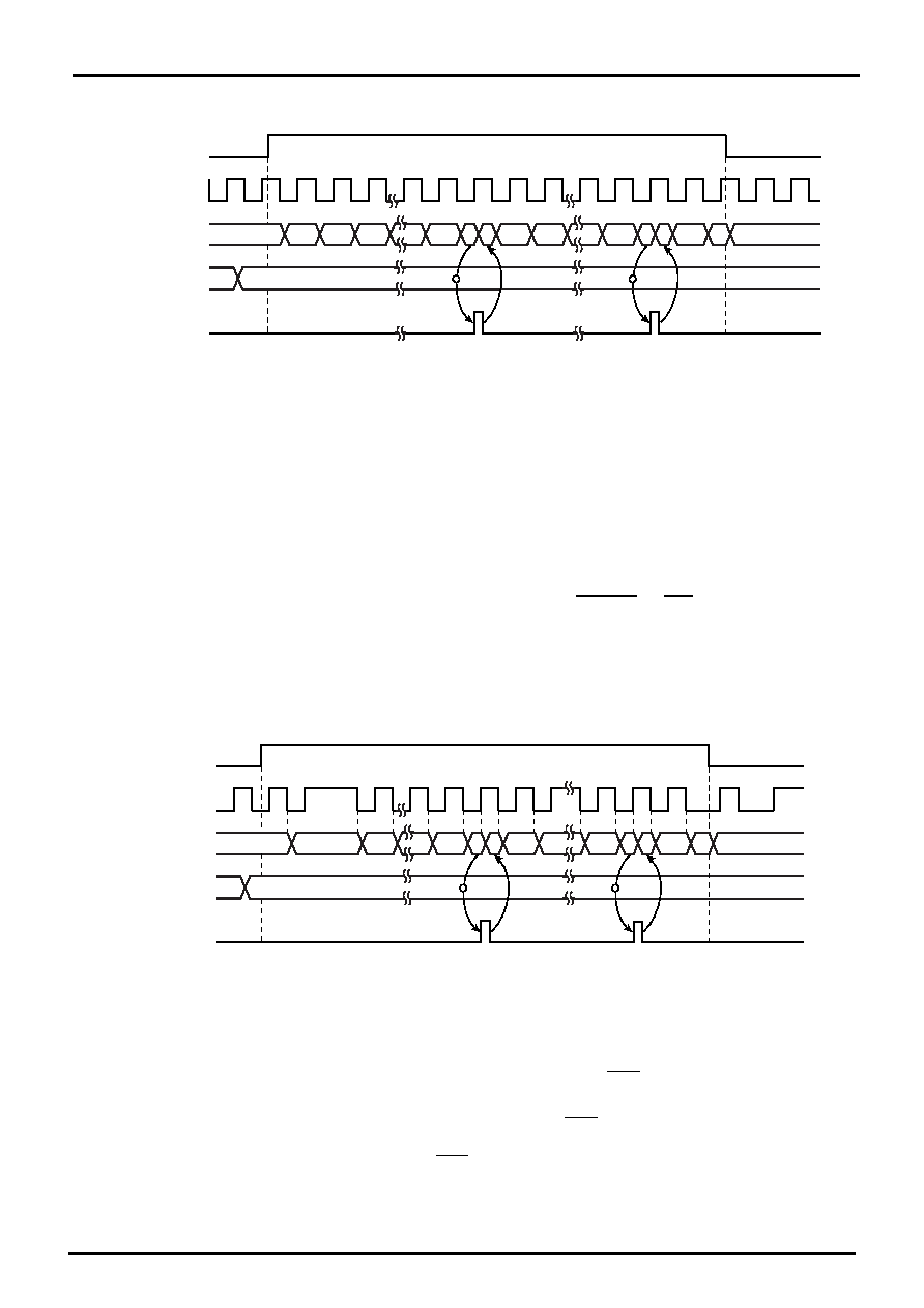
Figure 9-2 8-Bit Timer Mode Timing Chart (TC4)
9.3.2 8-Bit Event Counter Mode (TC3, 4)
In the 8-bit event counter mode, the up-counter counts up at the falling edge of the input pulse to the TCj pin.
When a match between the up-counter and the TTREGj value is detected, an INTTCj interrupt is generated and
the up-counter is cleared. After being cleared, the up-counter restarts counting at the falling edge of the input
pulse to the TCj pin. Two machine cycles are required for the low- or high-level pulse input to the TCj pin.
Therefore, a maximum frequency to be supplied is fc/24 Hz in the NORMAL1/2 or IDLE1/2 mode, and fs/24
Hz in the SLOW1/2 or SLEEP1/2 mode.
Note 1: In the event counter mode, fix TCjCR<TFFj> to 0. If not fixed, the PDOj, PWMj and PPGj pins may output
pulses.
Note 2: In the event counter mode, do not change the TTREGj setting while the timer is running. Since TTREGj is
not in the shift register configuration in the event counter mode, the new value programmed in TTREGj is in
effect immediately after the programming. Therefore, if TTREGi is changed while the timer is running, an
expected operation may not be obtained.
Note 3: j = 3, 4
Figure 9-3 8-Bit Event Counter Mode Timing Chart (TC4)
9.3.3 8-Bit Programmable Divider Output (PDO) Mode (TC3, 4)
This mode is used to generate a pulse with a 50% duty cycle from the PDOj pin.
In the PDO mode, the up-counter counts up using the internal clock. When a match between the up-counter
and the TTREGj value is detected, the logic level output from the PDOj pin is switched to the opposite state and
the up-counter is cleared. The INTTCj interrupt request is generated at the time. The logic state opposite to the
timer F/Fj logic level is output from the PDOj pin. An arbitrary value can be set to the timer F/Fj by
TCjCR<TFFj>. Upon reset, the timer F/Fj value is initialized to 0.
To use the programmable divider output, set the output latch of the I/O port to 1.
1
2
3
n-1
n 0
1
n-1
n
2
0
1
2
0
n
?
Internal
Source Clock
Counter
Match detect
Counter clear
Match detect
Counter clear
TC4CR<TC4S>
TTREG4
INTTC4 interrupt request
1
0
2
n-1
n 0
1
2
0
n
?
Counter
Match detect
Counter
clear
n-1
n
2
0
1
Match detect
Counter
clear
TC4CR<TC4S>
TTREG4
INTTC4 interrupt request
TC4 pin input
相關(guān)PDF資料 |
PDF描述 |
|---|---|
| TMP86CM29BU | 8-BIT, MROM, 16 MHz, MICROCONTROLLER, PQFP64 |
| TMP86FH09NG | 8-BIT, FLASH, 16 MHz, MICROCONTROLLER, PDIP32 |
| TMP86FS49BUG | 8-BIT, FLASH, 16 MHz, MICROCONTROLLER, PQFP64 |
| TMP86PS25F | 8-BIT, OTPROM, 16 MHz, MICROCONTROLLER, PQFP100 |
| TMP87C800N | 8-BIT, MROM, 8 MHz, MICROCONTROLLER, PDIP64 |
相關(guān)代理商/技術(shù)參數(shù) |
參數(shù)描述 |
|---|---|
| TMP86CH12MG | 制造商:TOSHIBA 制造商全稱(chēng):Toshiba Semiconductor 功能描述:8 Bit Microcontroller |
| TMP86CH21AUG | 制造商:TOSHIBA 制造商全稱(chēng):Toshiba Semiconductor 功能描述:8 Bit Microcontroller |
| TMP86CH21F | 制造商:TOSHIBA 制造商全稱(chēng):Toshiba Semiconductor 功能描述:CMOS 8-Bit Microcontroller |
| TMP86CH21U | 制造商:TOSHIBA 制造商全稱(chēng):Toshiba Semiconductor 功能描述:CMOS 8-Bit Microcontroller |
| TMP86CH22UG | 制造商:TOSHIBA 制造商全稱(chēng):Toshiba Semiconductor 功能描述:8 Bit Microcontroller |
發(fā)布緊急采購(gòu),3分鐘左右您將得到回復(fù)。