- 您現(xiàn)在的位置:買賣IC網(wǎng) > PDF目錄385873 > STA120 (意法半導(dǎo)體) DIGITAL AUDIO INTERFACE RECEIVER PDF資料下載
參數(shù)資料
| 型號: | STA120 |
| 廠商: | 意法半導(dǎo)體 |
| 英文描述: | DIGITAL AUDIO INTERFACE RECEIVER |
| 中文描述: | 數(shù)字音頻接口接收機(jī) |
| 文件頁數(shù): | 10/15頁 |
| 文件大?。?/td> | 183K |
| 代理商: | STA120 |
STA120
10/15
The validity flag indicates that the validity bit for a previous sample was high since the last clearing of the
error codes. The slipped sample error can only occur when FSYNC and SCK of the audio serial port are
inputs. In this case, if FSYNC is asynchronous to the received data rate, periodically a stereo sample will
be dropped or reread depending on whether the read rate is slower or faster than the received data rate .
When this occurs, the slipped sample error code will appear on the "E" pins.
The CRC error is updated at the beginning of a channel status block, and is only valid when the profes-
sional format of channel status data is received. This error is indicated when the STA120 calculated CRC
value does not match the CRC byte of the channel status block or when a block boundary changes (as in
removing samples while editing).
The parity error occurs when the incoming sub-frame does not have even parity as specified by the stan-
dards. The biphase coding error indicates a biphase coding violation occurred. The no lock error indicates
that the PLL is not locked onto the incoming data stream. Lock is achieved after receiving three frame pre-
ambles then one block preamble, and is lost after not receiving four consecutive frame preambles.
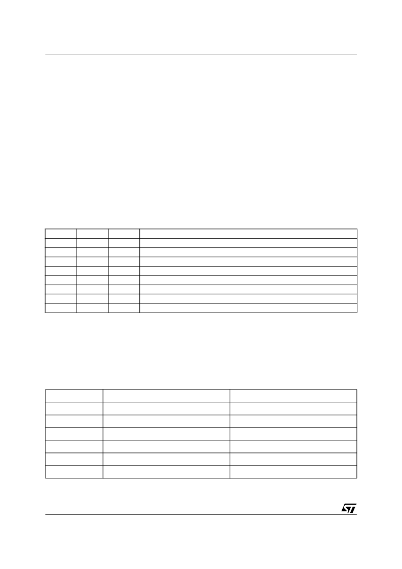
The receive frequency information is encoded on pins F2, F1 and F0, and is decoded as shown in Table
6. The on-chip frequency comparator compares the received clock frequency to an externally supplied
6.144MHz clock which is input on the FCK pin. The "F" pins. The clock on FCK must be valid for two thirds
of a block for the "F" pins to be accurate.
Table 4. Sample Frequency Decoding
Channel Status Reporting
When SEL is high, channel status is displayed on C0, and Ca-Ce for the channel selected by CS12. If
CS12 is low, channel status for sub-frame1 is displayed, and if CS12 is high, channel status for subframe
2 is displayed. the contents of Ca-Ce depend upon the C0 professional/consumer bit. The information re-
port is shown in Table 5.
Table 5. Channel Status Pins
F2
0
0
0
0
1
1
1
1
F1
0
0
1
1
0
0
1
1
F0
0
1
0
1
0
1
0
1
Error
Out of Range
48KHz ±4%
44.1KHz ±4%
32KHz ±4%
48KHz ±400ppm
44.1KHz ±400ppm
44.056KHz ±400ppm
32KHz ±400ppm
Pin
Professional
Consumer
C0
0 (low)
1 (high)
Ca
C1
C1
Cb
EM0
C2
Cc
EM1
C3
Cd
C9
ORIG
Ce
CRCE
IGCAT
相關(guān)PDF資料 |
PDF描述 |
|---|---|
| STA120D | DIGITAL AUDIO INTERFACE RECEIVER |
| STA2051 | 32-BIT SINGLE CHIP BASEBAND CONTROLLER FOR GPS AND TELEMATIC APPLICATIONS |
| STAC9204X5NBEYYX | 4-CHANNEL HD AUDIO CODEC WITH QUAD DIGITAL MICROPHONE INTERFACE |
| STAC9205D3TAEYYXR | 4-CHANNEL HD AUDIO CODEC WITH QUAD DIGITAL MICROPHONE INTERFACE |
| STAC9205D5NBEYYX | 4-CHANNEL HD AUDIO CODEC WITH QUAD DIGITAL MICROPHONE INTERFACE |
相關(guān)代理商/技術(shù)參數(shù) |
參數(shù)描述 |
|---|---|
| STA120D | 功能描述:音頻 DSP Audio Interfce Recvr RoHS:否 制造商:Texas Instruments 工作電源電壓: 電源電流: 工作溫度范圍: 安裝風(fēng)格: 封裝 / 箱體: 封裝:Tube |
| STA120D13TR | 功能描述:音頻 DSP Digital Audio Intrfc RoHS:否 制造商:Texas Instruments 工作電源電壓: 電源電流: 工作溫度范圍: 安裝風(fēng)格: 封裝 / 箱體: 封裝:Tube |
| STA120DJ | 制造商:STMicroelectronics 功能描述:DGTL AUD INTRFC RCVR 28SOIC - Rail/Tube |
| STA120DJ13TR | 功能描述:音頻 DSP Digital audio interface receiver RoHS:否 制造商:Texas Instruments 工作電源電壓: 電源電流: 工作溫度范圍: 安裝風(fēng)格: 封裝 / 箱體: 封裝:Tube |
| STA1210 | 制造商:M.E.C. Relays 功能描述: |
發(fā)布緊急采購,3分鐘左右您將得到回復(fù)。