- 您現(xiàn)在的位置:買(mǎi)賣(mài)IC網(wǎng) > PDF目錄383827 > SP8605 12-Bit Sampling A/D Converters PDF資料下載
參數(shù)資料
| 型號(hào): | SP8605 |
| 元件分類(lèi): | 串行ADC |
| 英文描述: | 12-Bit Sampling A/D Converters |
| 中文描述: | 12位采樣的A / D轉(zhuǎn)換器 |
| 文件頁(yè)數(shù): | 6/11頁(yè) |
| 文件大小: | 205K |
| 代理商: | SP8605 |

84
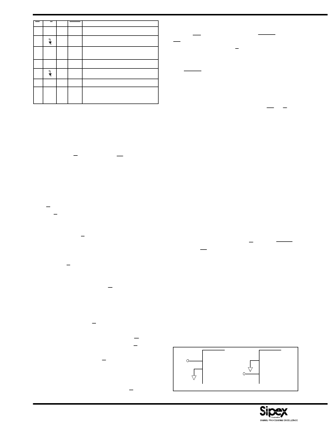
CS
R/C
HBE
BUSY
OPERATION
1
X
X
1
None – outputs in Hi-Z state.
0
1
0
0
1
Holds signal and initiates conversion.
0
1
0
1
Output three-state buffers enabled once
conversion has finished.
0
1
1
1
Enable hi-byte in 8-bit bus mode.
0
1
0
1
1
Inhibit start of conversion.
0
0
1
1
None – outputs in Hi-Z state.
X
X
X
0
Conversion in progress. Outputs Hi-Z
state. New conversion inhibited until
present conversion has finished.
Table 1. Control Line Functions
control lines are shown in
Table 1
.
For stand-alone operation, control of the
SP86XX
Series
is accomplished by a single control line
connected to R/C. In this mode, CS and HBE are
connected to GND. The output data are presented
as 12-bit words. The stand-alone mode is used in
systems containing dedicated input ports which do
not require full bus interface capability.
Conversion is initiated by a HIGH-to-LOW transition
on R/C. The three-state data output buffers are enabled
when R/C is HIGH and BUSY is HIGH. Thus, there
are two possible modes of operation: conversion can
be initiated with either positive or negative pulses. In
either case, the R/C pulse must remain LOW a
minimum of 40ns.
Figure 5
illustrates timing when conversion is initi-
ated by an R/C pulse which goes LOW and returns
HIGH during the conversion. In this case (Convert
Mode), the three-state outputs go into the Hi-Z state in
response to the falling edge of R/C, and are enabled for
external access to the data after completion of the
conversion.
Figure 6
illustrates the timing when conversion is
initiated by a positive R/C pulse. In this mode (Read
Mode), the output data from the previous conversion
is enabled during the HIGH portion of R/C. A new
conversion starts on the falling edge of R/C, and the
three-state outputs return to the Hi-Z state until the next
occurrence of a HIGH on R/C.
Conversion Start
A conversion is initiated on the
SP86XX Series
only
by a negative transition occurring on R/C, as shown
in
Table 2
. No other combination of states or transi-
tions will initiate a conversion. Conversion is inhibited
if either CS or HBE are HIGH, or if BUSY is LOW.
CS and HBE should be stable a minimum of 25ns
prior to the transition on R/C. Timing relationships for
start of conversion are illustrated in
Figure 7
.
The BUSY output indicates the current state of the
converter by being LOW only during conversion.
During this time the three-state output buffers remain
in a Hi-Z state, and therefore data cannot be read
during conversion. During this period, additional
transitions on the three digital inputs (CS, R/C and
HBE) will be ignored, so that conversion cannot be
prematurely terminated or restarted.
I
nternal Clock
The
SP86XX Series
has an internal clock that is
factory trimmed to achieve the typical conversion
times given in the specifications, and a maximum
conversion time over the full operating tempera-
ture range of 2.7
μ
s, 4.7
μ
s or 9.7
μ
s, depending on
the model. No external adjustments are required,
and with the guaranteed maximum acquisition
time of 300ns, throughput performance is assured
with convert pulses as close as 3
μ
s for the
SP8603
.
Reading Data
After conversion is initiated, the output buffers remain
in a Hi-Z state until the following three logic condi-
tions are simultaneously met: R/C is HIGH, BUSY is
HIGH and CS is LOW. Upon satisfying these condi-
tions, the data lines are enabled according to the state
of HBE. See
Figure 7
for timing relationships and
specifications.
CALIBRATION...
Optional External Gain And Offset Trim
Offset and full-scale errors may be trimmed to zero
using external offset and full-scale trim potenti-
ometers connected to the
SP86XX Series
as shown
in
Figure 3
.
If adjustment of offset and full scale is not required,
2
3
+10V
Input
SP8603/05/10
2
3
+5V
Input
SP8603/05/10
Figure 2. a) 10V Range b) 5V Range — Without Trims
相關(guān)PDF資料 |
PDF描述 |
|---|---|
| SPB16035 | Schottky Rectifier |
| SPB16040 | Schottky Rectifier |
| SPB16045 | Schottky Rectifier |
| SPW17N80C2 | TRANSISTOR | MOSFET | N-CHANNEL | 800V V(BR)DSS | 17A I(D) | TO-247VAR |
| SR-5R1 | ZUGENTLASTER FUER RUNDKABEL 6 BIS 7.4MM Inhalt pro Packung: 100 Stk. |
相關(guān)代理商/技術(shù)參數(shù) |
參數(shù)描述 |
|---|---|
| SP8607 | 制造商:ZARLINK 制造商全稱:Zarlink Semiconductor Inc 功能描述:emitter coupled logic divider |
| SP8607ACCM | 制造商:ZARLINK 制造商全稱:Zarlink Semiconductor Inc 功能描述:emitter coupled logic divider |
| SP8607ACM | 制造商:ZARLINK 制造商全稱:Zarlink Semiconductor Inc 功能描述:emitter coupled logic divider |
| SP8607BCM | 制造商:ZARLINK 制造商全稱:Zarlink Semiconductor Inc 功能描述:emitter coupled logic divider |
| SP-860-AR-SK | 功能描述:顯示開(kāi)發(fā)工具 Starter kit of SP-860 AR RoHS:否 制造商:4D Systems 產(chǎn)品:4Display Shields 工具用于評(píng)估:?OLED-160-G1, ?OLED-160-G2 接口類(lèi)型:Serial 工作電源電壓:5 V |
發(fā)布緊急采購(gòu),3分鐘左右您將得到回復(fù)。