- 您現(xiàn)在的位置:買賣IC網(wǎng) > PDF目錄98068 > S1C63408F0A0100 MICROCONTROLLER, PQFP128 PDF資料下載
參數(shù)資料
| 型號(hào): | S1C63408F0A0100 |
| 元件分類: | 微控制器/微處理器 |
| 英文描述: | MICROCONTROLLER, PQFP128 |
| 封裝: | PLASTIC, QFP-128 |
| 文件頁數(shù): | 4/151頁 |
| 文件大小: | 1171K |
| 代理商: | S1C63408F0A0100 |
第1頁第2頁第3頁當(dāng)前第4頁第5頁第6頁第7頁第8頁第9頁第10頁第11頁第12頁第13頁第14頁第15頁第16頁第17頁第18頁第19頁第20頁第21頁第22頁第23頁第24頁第25頁第26頁第27頁第28頁第29頁第30頁第31頁第32頁第33頁第34頁第35頁第36頁第37頁第38頁第39頁第40頁第41頁第42頁第43頁第44頁第45頁第46頁第47頁第48頁第49頁第50頁第51頁第52頁第53頁第54頁第55頁第56頁第57頁第58頁第59頁第60頁第61頁第62頁第63頁第64頁第65頁第66頁第67頁第68頁第69頁第70頁第71頁第72頁第73頁第74頁第75頁第76頁第77頁第78頁第79頁第80頁第81頁第82頁第83頁第84頁第85頁第86頁第87頁第88頁第89頁第90頁第91頁第92頁第93頁第94頁第95頁第96頁第97頁第98頁第99頁第100頁第101頁第102頁第103頁第104頁第105頁第106頁第107頁第108頁第109頁第110頁第111頁第112頁第113頁第114頁第115頁第116頁第117頁第118頁第119頁第120頁第121頁第122頁第123頁第124頁第125頁第126頁第127頁第128頁第129頁第130頁第131頁第132頁第133頁第134頁第135頁第136頁第137頁第138頁第139頁第140頁第141頁第142頁第143頁第144頁第145頁第146頁第147頁第148頁第149頁第150頁第151頁

S1C63406/408 TECHNICAL MANUAL
EPSON
93
CHAPTER 4: PERIPHERAL CIRCUITS AND OPERATION (Serial Interface)
Data
bus
Interrupt
request
Address
Error generation
Interrupt factor
flag ISER
Address
Interrupt mask
register EISER
Address
Receive completion
Interrupt factor
flag ISRC
Address
Interrupt mask
register EISRC
Address
Transmit completion
Interrupt factor
flag ISTR
Address
Interrupt mask
register EISTR
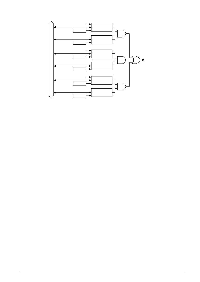
Fig. 4.11.8.1 Configuration of serial interface interrupt circuit
Transmit completion interrupt
This interrupt factor is generated at the point where the sending of the data written into the shift
register has been completed and sets the interrupt factor flag ISTR to "1". When set in this manner, if
the corresponding interrupt mask register EISTR is set to "1" and the CPU is set to interrupt enabled
status (I flag = "1"), an interrupt will be generated to the CPU.
When the interrupt mask register EISTR has been set to "0" and interrupt has been disabled, no
interrupt is generated to the CPU. Even in this case, the interrupt factor flag ISTR is set to "1".
The interrupt factor flag ISTR is reset to "0" by writing "1".
The following transmitting data can be set and the transmitting can be started (writing "1" to TXTRG)
after this interrupt factor occurs.
Receive completion interrupt
This interrupt factor is generated at the point where receiving has been completed and the receive
data incorporated into the shift register has been transferred into the receive data buffer and it sets the
interrupt factor flag ISRC to "1". When set in this manner, if the corresponding interrupt mask register
EISRC is set to "1" and the CPU is set to interrupt enabled status (I flag = "1"), an interrupt will be
generated to the CPU.
When the interrupt mask register EISRC has been set to "0" and interrupt has been disabled, no
interrupt is generated to the CPU. Even in this case, the interrupt factor flag ISRC is set to "1".
The interrupt factor flag ISRC is reset to "0" by writing "1".
The generation of this interrupt factor allows reading of the received data.
Also, the interrupt factor flag ISRC is set to "1" when a parity error or framing error is generated.
Error interrupt
This interrupt factor is generated at the point where a parity error, framing error or overrun error is
detected during receiving and it sets the interrupt factor flag ISER to "1". When set in this manner, if
the corresponding interrupt mask register EISER is set to "1" and the CPU is set to interrupt enabled
status (I flag = "1"), an interrupt will be generated to the CPU.
When the interrupt mask register EISER has been set to "0" and interrupt has been disabled, an
interrupt is not generated to the CPU. Even in this case, the interrupt factor flag ISER is set to "1".
The interrupt factor flag ISER is reset to "0" by writing "1".
Since all three types of errors result in the same interrupt factor, you should identify the error that has
been generated by the error flags PER (parity error), OER (overrun error) and FER (framing error).
相關(guān)PDF資料 |
PDF描述 |
|---|---|
| S1C63406D0A0100 | MICROCONTROLLER, UUC103 |
| S1C63455F | 4-BIT, MROM, 4.1 MHz, MICROCONTROLLER, PQFP128 |
| S1C63455D | 4-BIT, MROM, 4.1 MHz, MICROCONTROLLER, UUC105 |
| S1C63458F0A0100 | MICROCONTROLLER, PQFP144 |
| S1C63466D | 4-BIT, MROM, 4.1 MHz, MICROCONTROLLER, UUC140 |
相關(guān)代理商/技術(shù)參數(shù) |
參數(shù)描述 |
|---|---|
| S1C63557D04Q000 | 制造商:Seiko Instruments Inc (SII) 功能描述:EPSON MCU 4BIT |
| S1C63567 | 制造商:EPSON 制造商全稱:EPSON 功能描述:4-bit Single Chip Microcomputer |
| S1C63616 | 制造商:EPSON 制造商全稱:EPSON 功能描述:4-bit Single Chip Microcomputer |
| S1C63632 | 制造商:EPSON 制造商全稱:EPSON 功能描述:4-bit Single Chip Microcomputer |
| S1C63653 | 制造商:EPSON 制造商全稱:EPSON 功能描述:CMOS 4-bit Single Chip Microcontroller |
發(fā)布緊急采購(gòu),3分鐘左右您將得到回復(fù)。