- 您現(xiàn)在的位置:買賣IC網(wǎng) > PDF目錄373330 > RTL8204 Layout reference PDF資料下載
參數(shù)資料
| 型號: | RTL8204 |
| 英文描述: | Layout reference |
| 中文描述: | 布局參考 |
| 文件頁數(shù): | 6/7頁 |
| 文件大?。?/td> | 73K |
| 代理商: | RTL8204 |
8201layoutguide(V1.00)
2000-11-08
REALTEK
Chip design & System design
6
connect to Analog GND plane.
Digital GND: all GND pin of RTL8201 except Analog GND pin.
Digital Power: all VDD pin of RTL8201 except Analog power pins.
Analog GND: 29, 35, 45
Analog Power: 32, 36, 48
!
Both RJ-45 connector and the secondary side of the magnetic, which connects the
RJ-45 connector, use their own isolated ground. No power and ground planes exist
underneath this isolated area.
Fig 2. Isolate RJ-45 connector ground from system ground
6. Notice at ACR Card
!
If RTL8201 is connected to a controller watching for a wake-on-lan packet, you
may use 3.3Vaux supported by ACR slot as your power source for RTL8201 and its
related peripheral components. If other devices on ACR card also use the 3.3Vaux
power at the same time, the total current consumption supplied by 3.3Vaux on your
ACR card must lower than 0.375A to confirm to ACR specification.
!
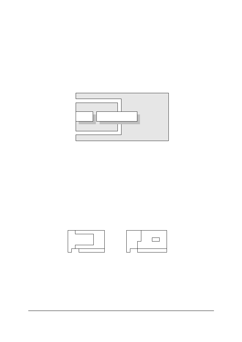
For better performance on GND plane at 2-Layer design, please follow as shown :
!
The MII interface of fast ethernet PHYceiver on ACR card is connected to primary
MII showed as ACR specification. Because the ACR specification is not defined
already, so if you want to produce the ACR card, please doubly check with the
chipset vendors and motherboard vendors.
GND
not good !
better !
GND
RJ-45
Magnetic
#
System Ground
$
Isolated
Ground
相關(guān)PDF資料 |
PDF描述 |
|---|---|
| RTL8305SB | RTL8305SB |
| RTL8316 | Specifications |
| RTL8801 | Specifications |
| RTM5070 | IR LEUCHTELEMENT ZUR FRONTPLATTENMONTAGE |
| RTP-PT100 | MESSFUEHLER PT100 EXTERN |
相關(guān)代理商/技術(shù)參數(shù) |
參數(shù)描述 |
|---|---|
| RTL8208 | 制造商:未知廠家 制造商全稱:未知廠家 功能描述:REALTEK SINGLE CHIP OCTAL 10/100 MBPS FAST ETHERNET TRANSCEIVER |
| RTL8208C-GR | 制造商:Realtek Semiconductor 功能描述: |
| RTL8208電路圖-1 | 制造商:未知廠家 制造商全稱:未知廠家 功能描述:RTL8208電路圖-1,RTL8204 |
| RTL8211 | 制造商:未知廠家 制造商全稱:未知廠家 功能描述: |
| RTL8211DG-VB-GR | 制造商:Realtek 功能描述:0 |
發(fā)布緊急采購,3分鐘左右您將得到回復(fù)。