- 您現(xiàn)在的位置:買賣IC網(wǎng) > PDF目錄373330 > RTL8204 Layout reference PDF資料下載
參數(shù)資料
| 型號(hào): | RTL8204 |
| 英文描述: | Layout reference |
| 中文描述: | 布局參考 |
| 文件頁(yè)數(shù): | 4/7頁(yè) |
| 文件大小: | 73K |
| 代理商: | RTL8204 |
8201layoutguide(V1.00)
2000-11-08
REALTEK
Chip design & System design
4
"
Avoid signal loss on these traces.
"
Tx+, Tx- should be equal length as possible.
Rx+, Rx- should be equal length as possible.
"
The distance between Tx
±
and Rx
±
:
TX+
TX-
RX+
RX-
Clock
L4
L3
L4
L3
L3 : < 1/10 inch= 0.25cm
L4 : need better isolation, ex: GND shielding
"
Rx
±
had better not using via, i.e., the Rx
±
traces at the component side.
"
Ferrite Beads should be close to chip pins and have the rating of
100
@100MHz
!
Keep the distance between the Tx and Rx signal pairs large, decrease the portion of
these two signal-pair traces going together in parallel. Furthermore, you can even
separate Ground planes underneath Tx and Rx signal pairs.
Magnetic
RTL8139x
Magnetic
RTL8139x
Rx
Tx
Rx
Tx
Fig 3. Separate Tx and Rx signal pairs
!
Magnetic: Any Magnetic with Tx/Rx turn ration of 1:1/1:1 are suitable for
RTL8201, such as Pulse PE68515/H1012, Valor ST6118, YCL 20PMT04, DELTA
LF8221, BH16ST8515, TAIMIC HSIP-002.
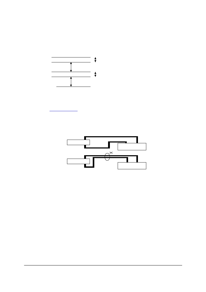
4. Trace Connection of MII Interface to LAN Controller
!
Following figure shows the RTL8201 Lan-on-Motherboard suggested trace lengths
using an optional CNR or ACR connector. We suggest the trace length between
LAN controller and RTL8201 should be as short as possible and if possible, and the
maximum trace length must be shorter than 10 inch.
!
As showed in following figure, please make sure that the length mismatch between
data signals and its related clock doesn’t exceed 1 inches, ex., the trace groups such
as TXD[0-3] and TXCLK, RXD[0-3] and RXCLK.
!
When RTL8201 links at 100M speed, the TXCLK and RXCLK is 25MHz clock to
相關(guān)PDF資料 |
PDF描述 |
|---|---|
| RTL8305SB | RTL8305SB |
| RTL8316 | Specifications |
| RTL8801 | Specifications |
| RTM5070 | IR LEUCHTELEMENT ZUR FRONTPLATTENMONTAGE |
| RTP-PT100 | MESSFUEHLER PT100 EXTERN |
相關(guān)代理商/技術(shù)參數(shù) |
參數(shù)描述 |
|---|---|
| RTL8208 | 制造商:未知廠家 制造商全稱:未知廠家 功能描述:REALTEK SINGLE CHIP OCTAL 10/100 MBPS FAST ETHERNET TRANSCEIVER |
| RTL8208C-GR | 制造商:Realtek Semiconductor 功能描述: |
| RTL8208電路圖-1 | 制造商:未知廠家 制造商全稱:未知廠家 功能描述:RTL8208電路圖-1,RTL8204 |
| RTL8211 | 制造商:未知廠家 制造商全稱:未知廠家 功能描述: |
| RTL8211DG-VB-GR | 制造商:Realtek 功能描述:0 |
發(fā)布緊急采購(gòu),3分鐘左右您將得到回復(fù)。