- 您現(xiàn)在的位置:買賣IC網(wǎng) > PDF目錄373330 > RTL8204 Layout reference PDF資料下載
參數(shù)資料
| 型號: | RTL8204 |
| 英文描述: | Layout reference |
| 中文描述: | 布局參考 |
| 文件頁數(shù): | 3/7頁 |
| 文件大?。?/td> | 73K |
| 代理商: | RTL8204 |
8201layoutguide(V1.00)
2000-11-08
REALTEK
Chip design & System design
3
cross the digital signals with Analog/Power, you had better a 90
°
cross
.
!
The trace length and the ratio of trace width to trace height above the ground planes
should be consider carefully. The clocks and other high speed signal trace should be
short and wide as possible. (compare with normal digital trace). It is better to have a
ground plane under these traces, and if possible, with GND plane around.
!
Trace length of a signal should not exceed 1/20 of the highest harmonic (about 10
th
)
wavelength. For example, the 25M clock trace should not exceed 30cm and the
125M signal traces should not exceed 12cm (Tx
±
, Rx
±
).
!
The trace of Power signal (de-couple cap traces, power traces, grounding traces)
should be short and wide, the VIAs of de-couple cap should be larger in diameter.
!
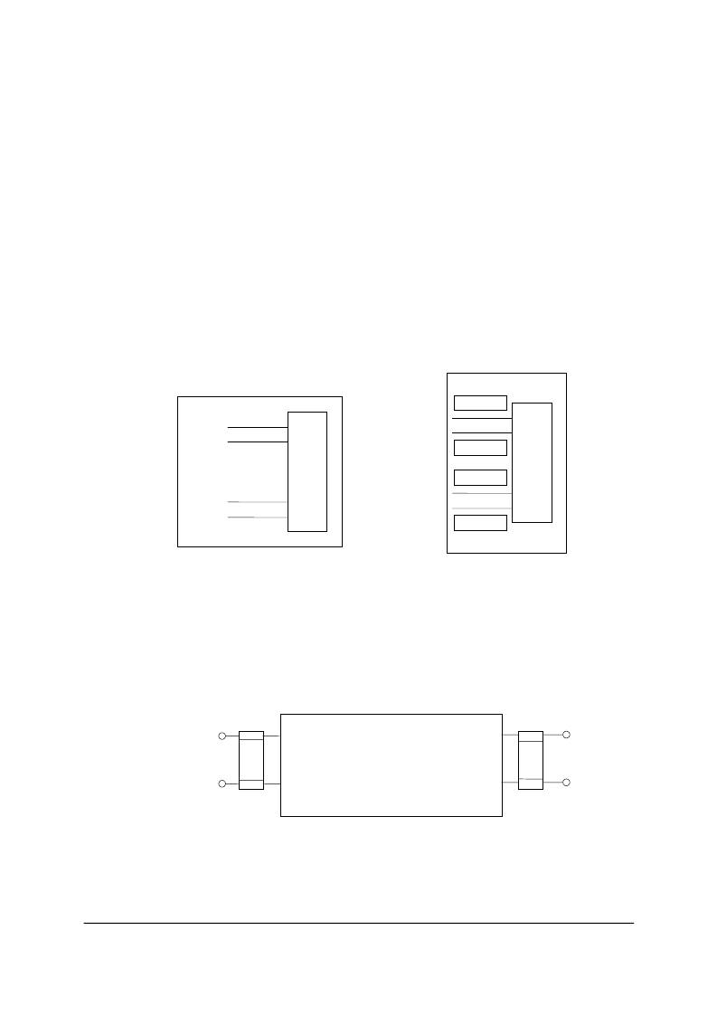
Each cap should have a separated VIA to GND. GND VIA should be within 0.2
inch. Avoid the following de-couple cap connection :
8
2
0
1
Rx-
Rx+
Tx-
Tx+
GND
GND
fair !
good !
8
2
0
1
Rx-
Rx+
Tx-
Tx+
GND
GND
GND
GND
GND
GND
!
De-couple cap
Should be placed as close to IC as pos., the traces should be short. Every RTL8201
analog power need de-couple (pin 32, 36, 48). Every RTL8201 digital power with a
de-couple cap will be better, especially, for 8, 14 pin (connected as follow).
8201
VDD
GND
14
17
8
11
VDD
GND
to power plane
to GND plane
!
Ferrite Bead placement: The bead connected to 32, 36, 48 should be close to
RTL8201, at least 48 pin must need beads (100M/100
).
!
Tx
±
, Rx
±
traces should pay more attention :
相關(guān)PDF資料 |
PDF描述 |
|---|---|
| RTL8305SB | RTL8305SB |
| RTL8316 | Specifications |
| RTL8801 | Specifications |
| RTM5070 | IR LEUCHTELEMENT ZUR FRONTPLATTENMONTAGE |
| RTP-PT100 | MESSFUEHLER PT100 EXTERN |
相關(guān)代理商/技術(shù)參數(shù) |
參數(shù)描述 |
|---|---|
| RTL8208 | 制造商:未知廠家 制造商全稱:未知廠家 功能描述:REALTEK SINGLE CHIP OCTAL 10/100 MBPS FAST ETHERNET TRANSCEIVER |
| RTL8208C-GR | 制造商:Realtek Semiconductor 功能描述: |
| RTL8208電路圖-1 | 制造商:未知廠家 制造商全稱:未知廠家 功能描述:RTL8208電路圖-1,RTL8204 |
| RTL8211 | 制造商:未知廠家 制造商全稱:未知廠家 功能描述: |
| RTL8211DG-VB-GR | 制造商:Realtek 功能描述:0 |
發(fā)布緊急采購,3分鐘左右您將得到回復(fù)。