- 您現(xiàn)在的位置:買賣IC網(wǎng) > PDF目錄367814 > PCE84C882 (NXP SEMICONDUCTORS) Microcontroller for monitor OSD and auto-sync applications(監(jiān)視器屏幕顯示和自動同步應(yīng)用的微控制器) PDF資料下載
參數(shù)資料
| 型號: | PCE84C882 |
| 廠商: | NXP SEMICONDUCTORS |
| 元件分類: | 微控制器/微處理器 |
| 英文描述: | Microcontroller for monitor OSD and auto-sync applications(監(jiān)視器屏幕顯示和自動同步應(yīng)用的微控制器) |
| 中文描述: | 8-BIT, MROM, 10 MHz, MICROCONTROLLER, PDIP42 |
| 封裝: | 0.600 INCH, PLASTIC, SDIP-42 |
| 文件頁數(shù): | 24/60頁 |
| 文件大小: | 409K |
| 代理商: | PCE84C882 |
第1頁第2頁第3頁第4頁第5頁第6頁第7頁第8頁第9頁第10頁第11頁第12頁第13頁第14頁第15頁第16頁第17頁第18頁第19頁第20頁第21頁第22頁第23頁當前第24頁第25頁第26頁第27頁第28頁第29頁第30頁第31頁第32頁第33頁第34頁第35頁第36頁第37頁第38頁第39頁第40頁第41頁第42頁第43頁第44頁第45頁第46頁第47頁第48頁第49頁第50頁第51頁第52頁第53頁第54頁第55頁第56頁第57頁第58頁第59頁第60頁
1996 Jan 08
24
Philips Semiconductors
Preliminary specification
Microcontroller for monitor OSD
and auto-sync applications
PCE84C882
10.2
Default values of OSD after Power-on-reset
Frequency of OSD clock: undefined, must be
programmed
Background/Shadowing mode: No background mode
Background/Shadowing colour: blue
Character size: 1H/1V
OSD disabled
Full 64 display RAM displayed (End of display bit = 0)
VOW1E and VOW0E disabled
Horizontal starting position: 5th dot
Vertical starting position: 256th scan-line
Polarity of HSYNCN: active LOW
Polarity of VSYNCN: active LOW
Output polarities of FB, VOW0 to VOW2: active HIGH
Blinking ratio: 3 : 1
Blinking frequency:
1
128
×
f
Vsync
Frame background colour: blue.
After a Power-on-reset, the OSD can be set-up as required
by selecting the Space Code as the first character
(address 0) and the Carriage Return Code as the next
character (address 1). This procedure allows the user to
select the initial background colour; character size and
inter-line spacing.
10.3
Loading character data into display RAM
Three Derivative Registers are used to address and load
data into the display RAM. These registers are described
below.
10.3.1
DCR A
DDRESS
R
EGISTER
(DCRAR)
This is Derivative Register 30 and holds the address of the
location in display RAM to which the data held in registers
DCRTR and DCRCR will be written to. 1 of 64 locations
can be addressed. Bits 7 and 6 are reserved. The contents
of this register are automatically incremented after each
write operation to a RAM address, and become zero on
overflow.
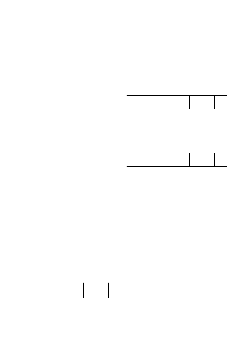
Table 13
DCR Address Register (DCRAR)
7
6
5
4
3
2
1
0
A5
A4
A3
A2
A1
A0
10.3.2
DCR A
TTRIBUTE
R
EGISTER
(DCRTR)
This is Derivative Register 31 and holds the character font
attribute data. The data will be loaded into bits <3-0> of the
location in RAM pointed to by the contents of DCRAR.
Bits 7 to 4 are reserved.
Table 14
DCR Attribute Register (DCRTR)
10.3.3
DCR C
HARACTER
R
EGISTER
(DCRCR)
This is Derivative Register 32 and holds the character data
that will be loaded into bits <9-4> of the location in RAM
addressed by the contents of DCRAR. Bits 7 and 6 are
reserved.
Table 15
DCR Character Register (DCRCR)
10.4
Writing character data into display RAM
The procedure for writing character data into the display
RAM is as follows:
1.
Select the start address in display RAM. The start
address is stored in DCRAR and can take any value
between 0 and 63.
2.
Load the character attributes into DCRTR. If the
attributes of a series of displayed characters are the
same, only DCRCR needs to be updated.
3.
Load the character data into DCRCR. The character
data will specify either a Character Font Code, the
Carriage Return Code or the Space Code. This
operation loads the selected RAM location with the
data held in registers DCRTR and DCRCR. The
address held in DCRAR is then incremented by ‘1’
pointing to the next RAM location in anticipation of the
next operation.
After a master reset the contents of DCRAR, DCRTR and
DCRCR are zero.
7
6
5
4
3
2
1
0
T3
T2
T1
T0
7
6
5
4
3
2
1
0
C5
C4
C3
C2
C1
C0
相關(guān)PDF資料 |
PDF描述 |
|---|---|
| PCF1171C | 4-digit LCD car clock(4數(shù)字LCD汽車時鐘) |
| PCF1171CT | 4-digit LCD car clock |
| PCF1171CU | 4-digit LCD car clock |
| PCF1172C | 3 1 /2 -digit LCD car clock(3 1 /2 數(shù)字 LCD汽車時鐘) |
| PCF1172CT | 31/2-digit LCD car clock |
相關(guān)代理商/技術(shù)參數(shù) |
參數(shù)描述 |
|---|---|
| PCE84C886 | 制造商:PHILIPS 制造商全稱:NXP Semiconductors 功能描述:Microcontroller for monitor OSD and auto-sync applications |
| PCEA02 | 制造商:ADAM-TECH 制造商全稱:Adam Technologies, Inc. 功能描述:.100&.156 RECEPTACLE WITH BOARD HOOKS |
| PCE-A-05 | 制造商:ADAM-TECH 制造商全稱:Adam Technologies, Inc. 功能描述:.100 RECEPTACLE WITH BOARD HOOKS |
| PCEA10 | 制造商:ADAM-TECH 制造商全稱:Adam Technologies, Inc. 功能描述:.100&.156 RECEPTACLE WITH BOARD HOOKS |
| PCEA20 | 制造商:ADAM-TECH 制造商全稱:Adam Technologies, Inc. 功能描述:.100&.156 RECEPTACLE WITH BOARD HOOKS |
發(fā)布緊急采購,3分鐘左右您將得到回復(fù)。