- 您現(xiàn)在的位置:買(mǎi)賣(mài)IC網(wǎng) > PDF目錄384801 > OX16CF950 (Electronic Theatre Controls, Inc.) LOW COST ASYNCHRONOUS 16 BIT CARD PDF資料下載
參數(shù)資料
| 型號(hào): | OX16CF950 |
| 廠(chǎng)商: | Electronic Theatre Controls, Inc. |
| 英文描述: | LOW COST ASYNCHRONOUS 16 BIT CARD |
| 中文描述: | 低成本異步16位卡 |
| 文件頁(yè)數(shù): | 13/60頁(yè) |
| 文件大小: | 753K |
| 代理商: | OX16CF950 |
第1頁(yè)第2頁(yè)第3頁(yè)第4頁(yè)第5頁(yè)第6頁(yè)第7頁(yè)第8頁(yè)第9頁(yè)第10頁(yè)第11頁(yè)第12頁(yè)當(dāng)前第13頁(yè)第14頁(yè)第15頁(yè)第16頁(yè)第17頁(yè)第18頁(yè)第19頁(yè)第20頁(yè)第21頁(yè)第22頁(yè)第23頁(yè)第24頁(yè)第25頁(yè)第26頁(yè)第27頁(yè)第28頁(yè)第29頁(yè)第30頁(yè)第31頁(yè)第32頁(yè)第33頁(yè)第34頁(yè)第35頁(yè)第36頁(yè)第37頁(yè)第38頁(yè)第39頁(yè)第40頁(yè)第41頁(yè)第42頁(yè)第43頁(yè)第44頁(yè)第45頁(yè)第46頁(yè)第47頁(yè)第48頁(yè)第49頁(yè)第50頁(yè)第51頁(yè)第52頁(yè)第53頁(yè)第54頁(yè)第55頁(yè)第56頁(yè)第57頁(yè)第58頁(yè)第59頁(yè)第60頁(yè)
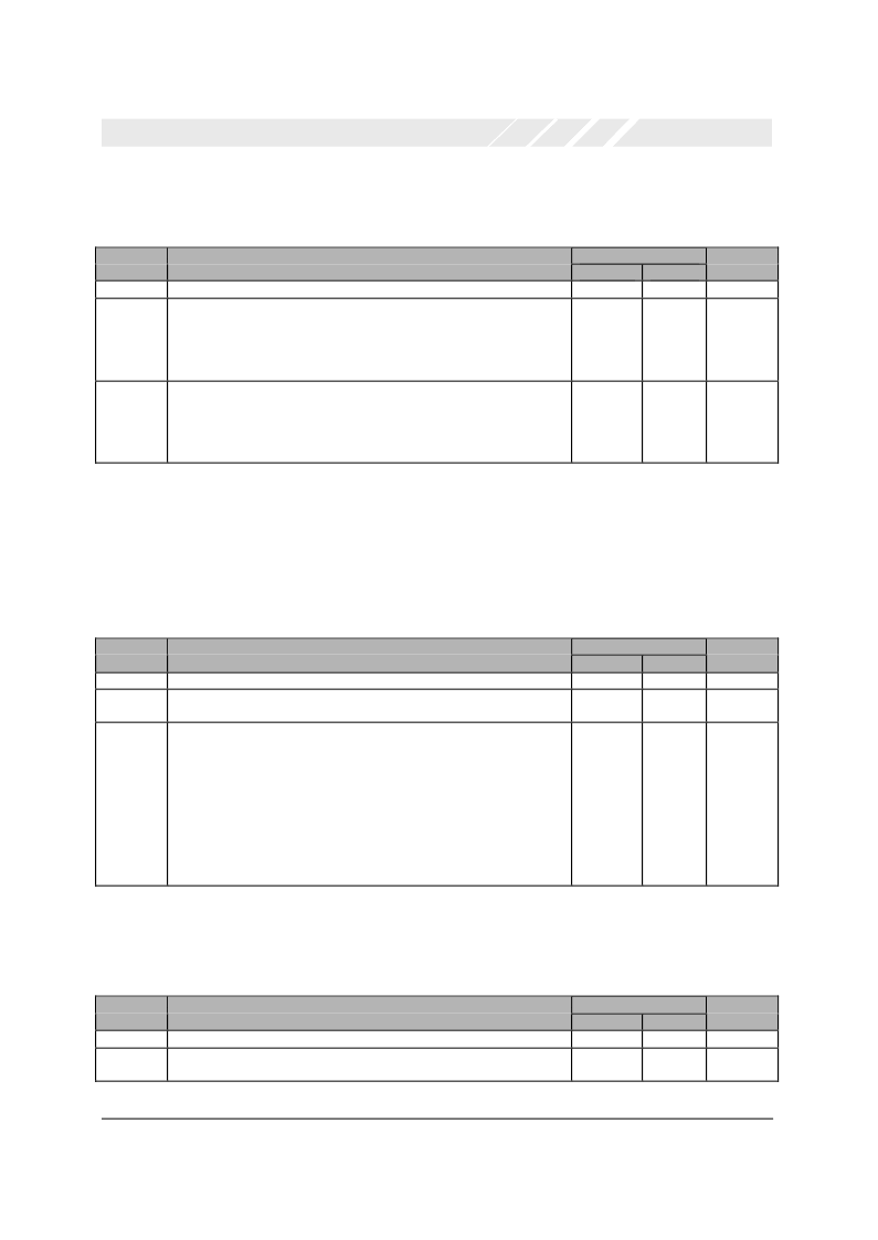
Multi-Purpose I/O Configuration register ‘MIC’ (Offset 0x09)
This register configures the operation for the multi-purpose I/O pins ‘MIO[1:0]’ as follows
Bits
Description
Page 13
OXCF950 DATA SHEET V1.1
OXFORD SEMICONDUCTOR LTD.
Read/Write
EEPROM
-
W
PCMCIA
R
R/W
Reset
7:4
3:2
Reserved
MIO1 Configuration register
00 -> MIO1 is a non-inverting input pin
01 -> MIO1 is an inverting input pin
10 -> MIO1 is an output pin driving ‘0’
11 -> MIO1 is an output pin driving ‘1’
MIO0 Configuration register
00 -> MIO0 is a non-inverting input pin
01 -> MIO0 is an inverting input pin
10 -> MIO0 is an output pin driving ‘0’
11 -> MIO0 is an output pin driving ‘1’
0000
00
1:0
W
R/W
00
Table 7: Multi Purpose I/O Configuration Register
UART Divider/Interrupt Pulse Width Divider register ‘DIV’ (Offset 0x0A)
This register defines the divide values (2^N division) for the clocks to the UART and Interrupt pulse generator signal. This allows
the device to be set up in its lowest power mode possible, and is fully programmable by the host or the EEPROM. The default
value for the UART clock divider provides a clock to the UART of x1. The default value for the Interrupt pulse divider provides a
clock to the interrupt processor of /32. See Section 5.4.1 Note that the UART clock rate should not be changed without then
resetting the UART(see SRT register).
Bits
Description
Read/Write
EEPROM
-
W
PCMCIA
R
R/W
Reset
7:6
5:3
Reserved
Uart clock divide value.
The division ratio is 2^N, giving 1, 2, 4, 8, 16, 32, 64, 128
Interrupt Pulse divide value:
This field should be set under the following clock freq. conditions
000 -> when clock frequency is less than 2MHz
001 -> when clock frequency is between 2 and 4MHz
010 -> when clock frequency is between 4 and 8MHz
011 -> when clock frequency is between 8 and 16MHz
100 -> when clock frequency is between 16 and 32MHz
101 -> when clock frequency is between 32 and 64MHz
110 ->
RESERVED
111 ->
RESERVED
00
000
2:0
W
R/W
101
Table 8: UART Divider/ Interrupt Pulse Width Divider
Mode Status register ‘MSR’ (Offset 0x0B)
This read only register return the state of the MODE pin (i.e. whether in Normal or Local Bus modes).
Bits
Description
Read/Write
EEPROM
-
-
PCMCIA
R
R
Reset
7:1
0
Reserved
Mode
O = Normal, 1 = Local Bus
0000000
X
Table 9: Mode Status Register
相關(guān)PDF資料 |
PDF描述 |
|---|---|
| OX2000A | OCXO |
| OX2020A | OCXO |
| OX2420A | OCXO |
| OX4020A | OCXO |
| OX4420A | OCXO |
相關(guān)代理商/技術(shù)參數(shù) |
參數(shù)描述 |
|---|---|
| OX16PCI952 | 制造商:OXFORD 制造商全稱(chēng):OXFORD 功能描述:Integrated High Performance Dual UARTs, Parallel Port and 5.0v PCI interface |
| OX16PCI952_05 | 制造商:OXFORD 制造商全稱(chēng):OXFORD 功能描述:Integrated High Performance Dual UARTs, Parallel Port and 5.0v PCI interface |
| OX16PCI952-TQAG | 制造商:PLX Technology 功能描述: 制造商:Oxford Semiconductor 功能描述:IC PCI BRIDGE DUAL PORT UART SMD |
| OX16PCI952-TQC60-A | 制造商:OXFORD 制造商全稱(chēng):OXFORD 功能描述:Integrated High Performance Dual UARTs, Parallel Port and 5.0v PCI interface |
| OX16PCI952-TQFP-A | 制造商:未知廠(chǎng)家 制造商全稱(chēng):未知廠(chǎng)家 功能描述:Integrated High Performance Dual UARTs, Parallel Port and 5.0v PCI interface |
發(fā)布緊急采購(gòu),3分鐘左右您將得到回復(fù)。