- 您現(xiàn)在的位置:買賣IC網(wǎng) > PDF目錄383723 > ORCAORT8850 Single 2.3V PNP in OP, I temp, -40C to +85C, 8-MSOP, T/R PDF資料下載
參數(shù)資料
| 型號(hào): | ORCAORT8850 |
| 英文描述: | Single 2.3V PNP in OP, I temp, -40C to +85C, 8-MSOP, T/R |
| 中文描述: | 現(xiàn)場(chǎng)可編程系統(tǒng)芯片(促進(jìn)文化基金)8通道x 850 Mbits /秒背板收發(fā)器 |
| 文件頁(yè)數(shù): | 34/90頁(yè) |
| 文件大小: | 1915K |
| 代理商: | ORCAORT8850 |
第1頁(yè)第2頁(yè)第3頁(yè)第4頁(yè)第5頁(yè)第6頁(yè)第7頁(yè)第8頁(yè)第9頁(yè)第10頁(yè)第11頁(yè)第12頁(yè)第13頁(yè)第14頁(yè)第15頁(yè)第16頁(yè)第17頁(yè)第18頁(yè)第19頁(yè)第20頁(yè)第21頁(yè)第22頁(yè)第23頁(yè)第24頁(yè)第25頁(yè)第26頁(yè)第27頁(yè)第28頁(yè)第29頁(yè)第30頁(yè)第31頁(yè)第32頁(yè)第33頁(yè)當(dāng)前第34頁(yè)第35頁(yè)第36頁(yè)第37頁(yè)第38頁(yè)第39頁(yè)第40頁(yè)第41頁(yè)第42頁(yè)第43頁(yè)第44頁(yè)第45頁(yè)第46頁(yè)第47頁(yè)第48頁(yè)第49頁(yè)第50頁(yè)第51頁(yè)第52頁(yè)第53頁(yè)第54頁(yè)第55頁(yè)第56頁(yè)第57頁(yè)第58頁(yè)第59頁(yè)第60頁(yè)第61頁(yè)第62頁(yè)第63頁(yè)第64頁(yè)第65頁(yè)第66頁(yè)第67頁(yè)第68頁(yè)第69頁(yè)第70頁(yè)第71頁(yè)第72頁(yè)第73頁(yè)第74頁(yè)第75頁(yè)第76頁(yè)第77頁(yè)第78頁(yè)第79頁(yè)第80頁(yè)第81頁(yè)第82頁(yè)第83頁(yè)第84頁(yè)第85頁(yè)第86頁(yè)第87頁(yè)第88頁(yè)第89頁(yè)第90頁(yè)
ORCAORT4622 FPSC
Four-Channel x 622 Mbits/s Backplane Transceiver
Preliminary Data Sheet
March 2000
34
L Lucent Technologies Inc.
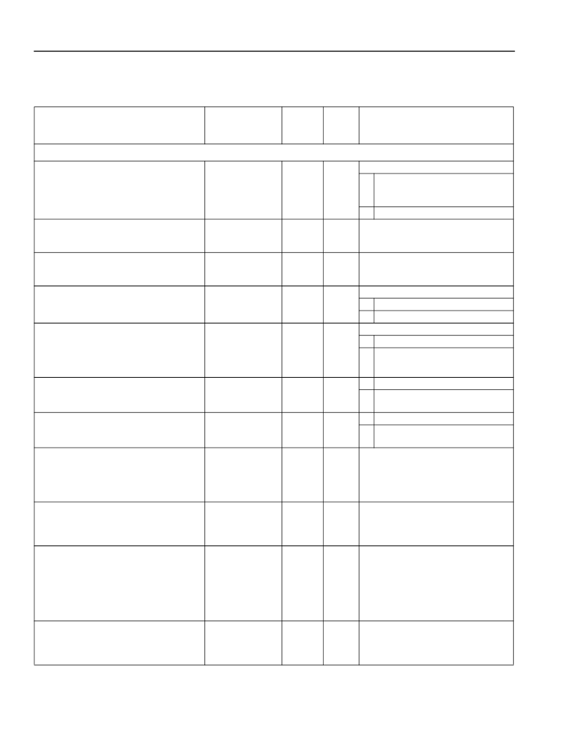
Memory Map
(continued)
Table 10. Memory Map Bit Descriptions
* The error insertion is based on a rising edge detector. As such, the control must be set to value 0 before trying to initiate a second A1/A2
corruption.
The error insertion is based on a rising edge detector. As such, the control must be set to value 0 before trying to initiate a second B1
corruption.
Bit/Register Name(s
)
Bit/ Register
Location (hex)
Register
Type
Default
Value
(hex)
Description
Channel Register Block (Channel A, Channel B, Channel C, Channel D)
(continued)
channel enable/disable control
20, 38, 50, 68 [5]
creg
0
Channel Enable/Disable Control
0
Powerdown channel A/B/C/D CDR
and LVDS I/O can be used with
data_rx_en to 3-state output buses.
1
Functional mode.
To be used as 3-state control for pro-
tection switching on the FPGA data
output.
To be used as 3-state control for TOH
data output. Only channel A enable sig-
nal is brought out.
Transmit Mode of Operation
0
Insert TOH from serial ports.
1
Pass through all TOH.
Other Registers
0
Insert TOH from serial ports.
1
Pass through that particular TOH
byte.
Hi-z control of parallel output bus.
20, 38, 50, 68 [6]
creg
0
Hi-z control of TOH data output.
20 [7]
creg
0
Tx mode of operation
21, 39, 51, 69 [7]
creg
0
Tx E1 F2 E2 source select
Tx S1 M0 source select
Tx K1 K2 source select
Tx D12—D9 source select
Tx D8—D1 source select
A1/A2 error insert command
21, 39, 51, 69 [6]
21, 39, 51, 69 [5]
21, 39, 51, 69 [4]
21, 39, 51, 69 [3:0]
22, 3a, 52, 6a [7:0]
23, 3b, 53, 6b [0]
creg
creg
creg
creg
creg
creg
0
0
0
4’h0
8’h00
0
0
1
Do not insert error.*
Insert error for number of frames in
register hex 0C.*
Do not insert error.
Insert error for one frame in B1 bits
defined by register hex 0F.
The value one in any bit location indi-
cates that STS# is in CONCAT mode.
A 0 indicates that the STS is not in
CONCAT mode, or is the head of a
concat group.
These flag register bits per STS-12
alarm flag, AIS-P flag, and elastic store
overflow flag are the per-channel inter-
rupt status (consolidation) register.
These are per the STS-12 alarm flags
with the corresponding enable/mask
register.
B1 error insert command
23, 3b, 53, 6b [1]
creg
0
0
1
concatindication 12, 9, 6, 3
concatindication 11, 8, 5, 2, 10, 7, 4, 1
24, 3c, 54, 6c [3:0]
25, 3d, 55, 6d [7:0]
sreg
sreg
0
0
per STS-12 alarm flag
AIS-P flag
elastic store overflow flag
enable/mask register [2:0]
FIFO aligner threshold error flag
receiver internal path parity error flag
LOF flag
LVDS link B1 parity error flag
input parallel bus parity error flag
TOH serial input port parity error flag
enable/mask register [5:0]
AIS interrupt flags 12, 9, 6, 3
AIS interrupt flags 11, 8, 5, 2, 10, 7, 4, 1
enable/mask register 12, 9, 6, 3
enable/mask register 11, 8, 5, 2, 10, 7, 4, 1
26, 3e, 56, 6e [0]
26, 3e, 56, 6e [1]
26, 3e, 56, 6e [2]
27, 3f, 57, 6f [2:0]
28, 40, 58, 70 [0]
28, 40, 58, 70 [1]
28, 40, 58, 70 [2]
28, 40, 58, 70 [3]
28, 40, 58, 70 [4]
28, 40, 58, 70 [5]
29, 41, 59, 71 [5:0]
2a, 42, 5a, 72 [3:0]
2b, 43, 5b, 73 [7:0]
2c, 44, 5c, 74 [3:0]
2d, 45, 5d, 75 [7:0]
isreg
isreg
isreg
iereg
iareg
iareg
iareg
iareg
iareg
iareg
iareg
iareg
iareg
iereg
iereg
0
0
0
3’b000
0
0
0
0
0
0
6’h00
4’h0
8’h00
4’h0
8’h00
These are the AIS-P alarm flags with
the corresponding enable/mask
register.
相關(guān)PDF資料 |
PDF描述 |
|---|---|
| ORD211 | REED SWITCH |
| ORD221 | REED SWITCH |
| ord9216 | Reed Switch(舌簧開關(guān)) |
| ORD9702R5 | Optoelectronic |
| ORD9702 | ; Rise Time:120ns; Fall Time:60ns; Package/Case:38-TSSOP; Number of Drivers:1; Supply Voltage Max:50V; Driver Type:MOSFET; Leaded Process Compatible:Yes; Operating Temp. Max:85 C; Operating Temp. Min:-20 C |
相關(guān)代理商/技術(shù)參數(shù) |
參數(shù)描述 |
|---|---|
| ORD 228VL/25-27 AT | 功能描述:磁性/簧片開關(guān) REED SWITCH Single-contact RoHS:否 制造商:MEDER electronic (Standex) 開關(guān)類型:Reed 觸點(diǎn)形式:1 Form A (SPST-NO) 觸點(diǎn)額定值:10 VA 操作范圍:10 At to 50 At 工作間隙: 磁鐵類型: 顏色: 端接類型:Axial 封裝:Bulk |
| ORD Module | 制造商:Emerson Network Power - Embedded Power 功能描述:ORD MODULE - Bulk |
| ORD# 10549117 | 制造商:Amphenol Corporation 功能描述:ORD# 10549117-PER DAN D. - Bulk |
| ORD211 | 制造商:MEDER 制造商全稱:Meder Electronic 功能描述:REED SWITCH |
| ORD211(0810) | 制造商:OKI Semiconductor 功能描述: |
發(fā)布緊急采購(gòu),3分鐘左右您將得到回復(fù)。