- 您現(xiàn)在的位置:買賣IC網(wǎng) > PDF目錄370849 > M37736EHL (Mitsubishi Electric Corporation) PROM VERSION OF M37736MHLXXXHP(MICROCOMPUTERS) PDF資料下載
參數(shù)資料
| 型號(hào): | M37736EHL |
| 廠商: | Mitsubishi Electric Corporation |
| 英文描述: | PROM VERSION OF M37736MHLXXXHP(MICROCOMPUTERS) |
| 中文描述: | PROM的版本M37736MHLXXXHP(微型) |
| 文件頁(yè)數(shù): | 7/96頁(yè) |
| 文件大小: | 1328K |
| 代理商: | M37736EHL |
第1頁(yè)第2頁(yè)第3頁(yè)第4頁(yè)第5頁(yè)第6頁(yè)當(dāng)前第7頁(yè)第8頁(yè)第9頁(yè)第10頁(yè)第11頁(yè)第12頁(yè)第13頁(yè)第14頁(yè)第15頁(yè)第16頁(yè)第17頁(yè)第18頁(yè)第19頁(yè)第20頁(yè)第21頁(yè)第22頁(yè)第23頁(yè)第24頁(yè)第25頁(yè)第26頁(yè)第27頁(yè)第28頁(yè)第29頁(yè)第30頁(yè)第31頁(yè)第32頁(yè)第33頁(yè)第34頁(yè)第35頁(yè)第36頁(yè)第37頁(yè)第38頁(yè)第39頁(yè)第40頁(yè)第41頁(yè)第42頁(yè)第43頁(yè)第44頁(yè)第45頁(yè)第46頁(yè)第47頁(yè)第48頁(yè)第49頁(yè)第50頁(yè)第51頁(yè)第52頁(yè)第53頁(yè)第54頁(yè)第55頁(yè)第56頁(yè)第57頁(yè)第58頁(yè)第59頁(yè)第60頁(yè)第61頁(yè)第62頁(yè)第63頁(yè)第64頁(yè)第65頁(yè)第66頁(yè)第67頁(yè)第68頁(yè)第69頁(yè)第70頁(yè)第71頁(yè)第72頁(yè)第73頁(yè)第74頁(yè)第75頁(yè)第76頁(yè)第77頁(yè)第78頁(yè)第79頁(yè)第80頁(yè)第81頁(yè)第82頁(yè)第83頁(yè)第84頁(yè)第85頁(yè)第86頁(yè)第87頁(yè)第88頁(yè)第89頁(yè)第90頁(yè)第91頁(yè)第92頁(yè)第93頁(yè)第94頁(yè)第95頁(yè)第96頁(yè)
7
PRELIMINARY
Notice: This is not a final specification.
Some parametric limits are subject to change.
MITSUBISHI MICROCOMPUTERS
M37736MHBXXXGP
SINGLE-CHIP 16-BIT CMOS MICROCOMPUTER
CENTRAL PROCESSING UNIT (CPU)
The CPU has ten registers and is shown in Figure 3. Each of these
registers is described below.
ACCUMULATOR A (A)
Accumulator A is the main register of the microcomputer. It consists
of 16 bits and the low-order 8 bits can be used separately. The data
length flag (m) determines whether the register is used as a 16-bit
register or as an 8-bit register. It is used as a 16-bit register when flag
m is “0” and as an 8-bit register when flag m is “1”. Flag m is a part of
the processor status register (PS) which is described later.
Data operations such as arithmetic operation, data transfer, input/
output, etc., are executed mainly through the accumulator A.
ACCUMULATOR B (B)
Accumulator B has the same functions as accumulator A, but the
use of accumulator B requires more instruction bytes and execution
cycles than accumulator A.
INDEX REGISTER X (X)
Index register X consists of 16 bits and the low-order 8 bits can be
used separately. The index register length flag (x) determines whether
the register is used as a 16-bit register or as an 8-bit register. It is
used as a 16-bit register when flag x is “0” and as an 8-bit register
when flag x is “1”. Flag x is a part of the processor status register
(PS) which is described later.
In an index addressing mode where register X is used as the index
register, the contents of this address is added to obtain the real
address.
Also, when executing a block transfer instruction (MVP, MVN), the
contents of index register X indicates the low-order 16 bits of the
source data address. The third byte of the MVP or MVN is the high-
order 8 bits of the source data address.
INDEX REGISTER Y (Y)
Index register Y consists of 16 bits and the low-order 8 bits can be
used separately. The index register length flag (x) determines whether
the register is used as a 16-bit register or as an 8-bit register. It is
used as a 16-bit register when flag x is “0” and as an 8-bit register
when flag x is “1”. Flag x is a part of the processor status register
(PS) which is described later.
In an index addressing mode where register Y is used as the index
register, the contents of this address is added to obtain the real
address.
Also, when executing a block transfer instruction (MVP, MVN), the
contents of index register Y indicates the low-order 16 bits of the
destination data address. The second byte of the MVP or MVN is the
high-order 8 bits of the destination data address.
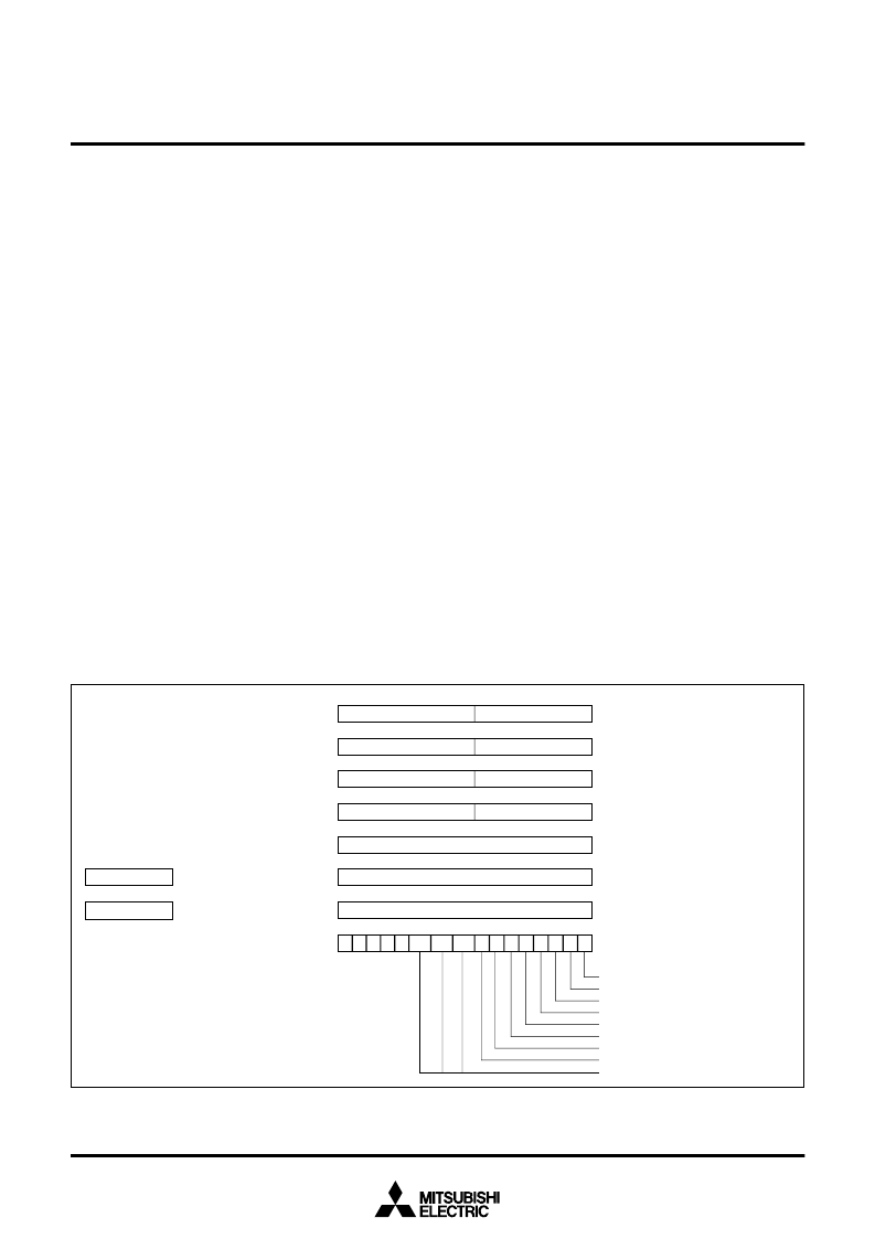
Fig. 3 Register structure
7
0
PG
Program bank register (PG)
7
0
DT
Data bank register (DT)
Carry flag
Zero frag
Interrupt disable flag
Decimal mode flag
Index register length flag
Data length flag
Overflow flag
Negative flag
Processor interrupt priority level (IPL)
Accumulator A (A)
Accumulator B (B)
Index register X (X)
Index register Y (Y)
Stack pointer (S)
Program counter (PC)
Direct page register (DPR)
Processor status register (PS)
0
A
H
A
L
15
0
7
B
H
B
L
15
0
7
X
H
X
L
15
0
7
Y
H
Y
L
15
0
7
15
0
PC
15
0
15
0
DPR
7
N
15
0
C
IPL
2
IPL
0
IPL
1
Z
I
D
x
m
V
0 0 0 0
S
相關(guān)PDF資料 |
PDF描述 |
|---|---|
| M37736EHBGS | PROM VERSION OF M37736EHBXXXGP |
| M37736EHLXXXHP | PROM VERSION OF M37736MHLXXXHP(MICROCOMPUTERS) |
| M37736MHLXXXHP | SINGLE-CHIP 16-BIT CMOS MICROCOMPUTER |
| M37736EHBXXXGP | PROM VERSION OF M37736MHBXXXGP(MICROCOMPUTERS) |
| M37736MHBXXXGP | SINGLE-CHIP 16-BIT CMOS MICROCOMPUTER |
相關(guān)代理商/技術(shù)參數(shù) |
參數(shù)描述 |
|---|---|
| M37736EHLXXXHP | 制造商:RENESAS 制造商全稱:Renesas Technology Corp 功能描述:PROM VERSION OF M37736MHLXXXHP |
| M37736M4B | 制造商:MITSUBISHI 制造商全稱:Mitsubishi Electric Semiconductor 功能描述:SINGLE-CHIP 16-BIT CMOS MICROCOMPUTER |
| M37736M4BXXXGP | 制造商:MITSUBISHI 制造商全稱:Mitsubishi Electric Semiconductor 功能描述:SINGLE-CHIP 16-BIT CMOS MICROCOMPUTER |
| M37736M4L | 制造商:MITSUBISHI 制造商全稱:Mitsubishi Electric Semiconductor 功能描述:SINGLE-CHIP 16-BIT CMOS MICROCOMPUTER |
| M37736M4LXXXHP | 制造商:MITSUBISHI 制造商全稱:Mitsubishi Electric Semiconductor 功能描述:SINGLE-CHIP 16-BIT CMOS MICROCOMPUTER |
發(fā)布緊急采購(gòu),3分鐘左右您將得到回復(fù)。