- 您現(xiàn)在的位置:買賣IC網(wǎng) > PDF目錄385472 > LH79525N0Q100A1 (NXP Semiconductors N.V.) System-on-Chip PDF資料下載
參數(shù)資料
| 型號: | LH79525N0Q100A1 |
| 廠商: | NXP Semiconductors N.V. |
| 元件分類: | 數(shù)學(xué)處理器 |
| 英文描述: | System-on-Chip |
| 封裝: | LH79524N0F100A1<SOT1019-1 (LFBGA208)|<<http://www.nxp.com/packages/SOT1019-1.html<1<Always Pb-free,;LH79525N0Q100A1<SOT1017-1 (LQFP176)|<<http://www.nxp.com/packages/SOT1 |
| 文件頁數(shù): | 22/64頁 |
| 文件大小: | 970K |
| 代理商: | LH79525N0Q100A1 |
第1頁第2頁第3頁第4頁第5頁第6頁第7頁第8頁第9頁第10頁第11頁第12頁第13頁第14頁第15頁第16頁第17頁第18頁第19頁第20頁第21頁當(dāng)前第22頁第23頁第24頁第25頁第26頁第27頁第28頁第29頁第30頁第31頁第32頁第33頁第34頁第35頁第36頁第37頁第38頁第39頁第40頁第41頁第42頁第43頁第44頁第45頁第46頁第47頁第48頁第49頁第50頁第51頁第52頁第53頁第54頁第55頁第56頁第57頁第58頁第59頁第60頁第61頁第62頁第63頁第64頁
LH79524/LH79525
System-on-Chip
22
Rev. 01
—
16 July 2007
Preliminary data sheet
NXP Semiconductors
DMA Controller
The DMA Controller provides support for DMA-capa-
ble peripherals. The LCD controller uses its own DMA
port, connecting directly to memory for retrieving dis-
play data.
Simultaneous servicing of up to 4 data streams
Three transfer modes are supported:
– Memory to Memory
– Peripheral to Memory
– Memory to Peripheral
Identical source and destination capabilities
Transfer Size Programmable (byte, half-word, word)
Burst Size Programmable
Address Increment or Address Freeze
Transfer Error interrupt for each stream
16-word FIFO array with pack and unpack logic
Handles all combinations of byte, half-word or word
transfers from input to output.
Color LCD Controller (CLCDC)
The CLCDC provides all the necessary control and
drive signals to interface directly with a variety of color
and monochrome LCD panels.
LH79524 has 16 LCD Data bits; LH79525 has 12
LCD Data bits.
Supports single and dual scan color and mono-
chrome Super Twisted Nematic (STN) displays with
4- or 8-bit interfaces (LH79524 only)
Supports Thin Film Transistor (TFT) color displays
Programmable resolution up to 1,024 × 1,024
15 gray-level mono, 3,375 color STN, and 64 k color
TFT support
1, 2, or 4 bits-per-pixel
(BPP) for monochrome STN
1-, 2-, 4-, or 8-BPP palettized color displays for color
STN and TFT (1-, 2-, or 4-bit only on LH79525)
True-color non-palettized, for color STN and TFT
Programmable timing for different display panels
256-entry, 16-bit palette fast-access RAM
Frame, line and pixel clock signals
AC bias signal for STN or data enable signal for
TFT panels
Patented grayscale algorithm
Interrupt Generation Events
Dual 16-deep programmable 32-bit wide FIFOs for
buffering incoming data.
ADVANCED LCD INTERFACE
The Advanced LCD Interface (ALI) allows for direct
connection to ultra-thin panels that do not include a tim-
ing ASIC. It converts TFT signals from the Color LCD
controller to provide the proper signals, timing and levels
for direct connection to a panel’s Row and Column driv-
ers for AD-TFT, HR-TFT, or any technology of panel that
allows for a connection of this type. The Advanced LCD
Interface peripheral also provides a bypass mode that
allows the LH79524/LH79525 to interface to the built-in
timing ASIC in standard TFT and STN panels.
Synchronous Serial Port (SSP)
The SSP is a master or slave interface for synchro-
nous serial communication with master or slave periph-
eral devices that support protocols for Motorola SPI,
National Semiconductor MICROWIRE, or Texas Instru-
ments Synchronous Serial Interface.
Master or slave operation
Programmable clock rate
Separate transmit FIFO and receive FIFO buffers, 16
bits wide, 8 locations deep
DMA for transmit and receive
Programmable interface protocols: Motorola SPI,
National Semiconductor MICROWIRE, or Texas
Instruments Synchronous Serial Port
Programmable data frame size from 4 to 16 bits
Independent masking of transmit FIFO, receive FIFO
and receive overrun interrupts
Available internal loopback test mode.
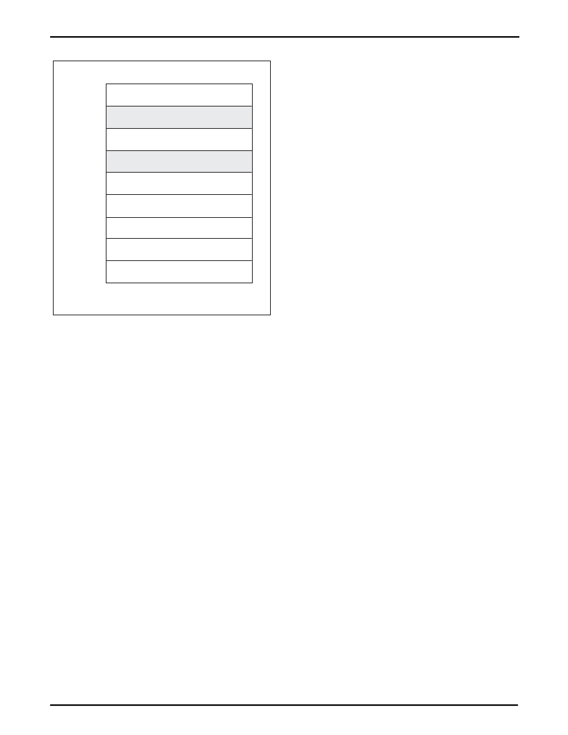
Figure 8. Memory Remap ‘11’
LH79525-18
ADVANCED HIGH-PERFORMANCE BUS
PERIPHERALS
ADVANCED PERIPHERAL BUS
PERIPHERALS
RESERVED
EXTERNAL SRAM nCS0
REMAP = 11
EXTERNAL STATIC MEMORY
EXTERNAL SDRAM
16KB INTERNAL SRAM
BOOT ROM
RESERVED
0xFFFFFFFF
0xFFFF1000
0xFFFF0000
0xFFFC0000
0xA0000000
0x80000000
0x60000000
0x40000000
0x20000000
0x00000000
相關(guān)PDF資料 |
PDF描述 |
|---|---|
| LH7A400N0F000B5 | 32-Bit System-on-Chip |
| LH7A400N0F076B5 | 32-Bit System-on-Chip |
| LH7A400N0G000B5 | 32-Bit System-on-Chip |
| LH7A404N0F000B3 | 32-Bit System-on-Chip |
| LH7A404N0F092B3 | 32-Bit System-on-Chip |
相關(guān)代理商/技術(shù)參數(shù) |
參數(shù)描述 |
|---|---|
| LH79525N0Q100A1,55 | 功能描述:ARM微控制器 - MCU LCD,USB,ETH’NET,MMU,ADC,QFP176 RoHS:否 制造商:STMicroelectronics 核心:ARM Cortex M4F 處理器系列:STM32F373xx 數(shù)據(jù)總線寬度:32 bit 最大時鐘頻率:72 MHz 程序存儲器大小:256 KB 數(shù)據(jù) RAM 大小:32 KB 片上 ADC:Yes 工作電源電壓:1.65 V to 3.6 V, 2 V to 3.6 V, 2.2 V to 3.6 V 工作溫度范圍:- 40 C to + 85 C 封裝 / 箱體:LQFP-48 安裝風(fēng)格:SMD/SMT |
| LH79525N0Q100A1,551 | 制造商:NXP Semiconductors 功能描述: |
| LH79525N0Q100A1;55 | 功能描述:ARM微控制器 - MCU LCD USB ETH’NET MMU RoHS:否 制造商:STMicroelectronics 核心:ARM Cortex M4F 處理器系列:STM32F373xx 數(shù)據(jù)總線寬度:32 bit 最大時鐘頻率:72 MHz 程序存儲器大小:256 KB 數(shù)據(jù) RAM 大小:32 KB 片上 ADC:Yes 工作電源電壓:1.65 V to 3.6 V, 2 V to 3.6 V, 2.2 V to 3.6 V 工作溫度范圍:- 40 C to + 85 C 封裝 / 箱體:LQFP-48 安裝風(fēng)格:SMD/SMT |
| LH79525N0Q100A155 | 制造商:Rochester Electronics LLC 功能描述: 制造商:NXP 功能描述: 制造商:NXP Semiconductors 功能描述: |
| LH79525N0Q100A1557 | 制造商:Rochester Electronics LLC 功能描述: 制造商:NXP 功能描述: 制造商:NXP Semiconductors 功能描述: |
發(fā)布緊急采購,3分鐘左右您將得到回復(fù)。