- 您現(xiàn)在的位置:買賣IC網(wǎng) > PDF目錄371797 > HDMP-2689 Quad 2.125/1.0625 GBd Fibre Channel General Purpose SerDes PDF資料下載
參數(shù)資料
| 型號(hào): | HDMP-2689 |
| 英文描述: | Quad 2.125/1.0625 GBd Fibre Channel General Purpose SerDes |
| 中文描述: | 四2.125/1.0625 GBd光纖通道通用的SerDes |
| 文件頁(yè)數(shù): | 18/28頁(yè) |
| 文件大小: | 356K |
| 代理商: | HDMP-2689 |
第1頁(yè)第2頁(yè)第3頁(yè)第4頁(yè)第5頁(yè)第6頁(yè)第7頁(yè)第8頁(yè)第9頁(yè)第10頁(yè)第11頁(yè)第12頁(yè)第13頁(yè)第14頁(yè)第15頁(yè)第16頁(yè)第17頁(yè)當(dāng)前第18頁(yè)第19頁(yè)第20頁(yè)第21頁(yè)第22頁(yè)第23頁(yè)第24頁(yè)第25頁(yè)第26頁(yè)第27頁(yè)第28頁(yè)

18
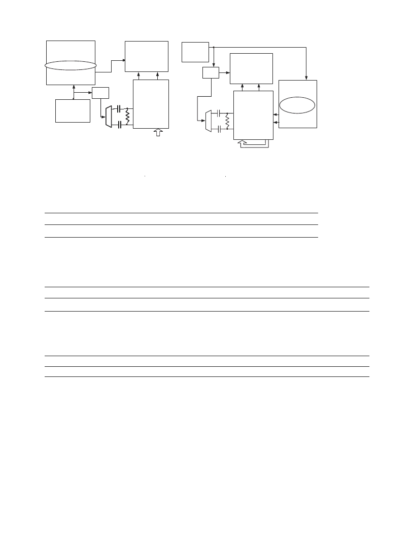
a) BLOCK DIAGRAM OF RJ MEASUREMENT METHOD
b) BLOCK DIAGRAM OF DJ MEASUREMENT METHOD
2.125 GHz
106.25 MHz
*PATTERN GENERATOR
PROVIDES PATTERN-
SYNCHRONOUS TRIGGER
70311A
CLOCK
SOURCE
Static K28.7 from pattern generator
or user pattern controlled by MDIO
HDMP-2689
RFCN
RFCP
TXnP
TXnN
TDn[9:0]
100
0.1
μ
F
0.1
μ
F
Balun
Balun
CH1
CH2
83480A
OSCILLOSCOPE
TRIGGER
HDMP-2689
RFCN
RFCP
TXnP
TXnN
RDn[9:0]
RXnP
RXnN
2.125 GHz
70311A
CLOCK
SOURCE
-Data
70841B
PATTERN
GENERATOR*
+K28.5, -K28.5
or CRPAT
+Data
106.25 MHz
TDn[9:0]
DIVIDE
BY 20
Trigger Out
Clock In
70841B
PATTERN
GENERATOR*
0011111100 static K28.7
DIVIDE
BY 20
83480A
OSCILLOSCOPE
CH1
CH2
TRIGGER
100
0.1
μ
F
0.1
μ
F
Figure 20. Transmitter DJ and RJ Measurement Method.
Table 19 . Pin Input Capacitance.
Symbol
Parameters
Units
Min
Typ
Max
CINPUT
Input Capacitance on SSTL Input pins
pF
1.1
Package Information
Package Thermal Characteristics
Symbol
Parameter
Units
Typ
Max
P
Dmax
Power Dissipation
W
2.5
θ
JA[1]
Thermal Resistance: Junction to Ambient
Air Flow (LFPM)
0
200
400
600
°
C/W
°
C/W
°
C/W
°
C/W
27.8
24.3
23.1
22.1
Ψ
JT[2]
Thermal Characterization parameter: Junction to package top
°
C/W
4.8
Ψ
JB[3]
Thermal Characterization parameter: Junction to board
°
C/W
19.3
Notes:
Based on independent package testing done by Agilent,
1.
θ
JA
is based on thermal measurement in still air environment at 25
°
C on a standard 4 x 4
”
FR4 PCB as specified in EIA/JESD 51-9.
2.
Ψ
JT
is used to determine the actual junction temperature in a given application, using the following equation:
T
J
=
Ψ
JT
x P
D
+ T
T
where T
T
is the measured temperature on top center of the package (also known as Case temperature, Tc) and P
D
is the power being
dissipated.
3.
Ψ
JB
is used to determine the actual junction temperature in a given application, using the following equation:
T
J
=
Ψ
JB
x P
D
+ T
B
where T
B
is measured board temperature, along the side of package at center on board surface and P
D
is the power being dissipated.
相關(guān)PDF資料 |
PDF描述 |
|---|---|
| HDMP1526 | Optoelectronic |
| HDMP2003 | FIBER OPTIC SUPPORT CIRCUIT |
| HDMP2004 | FIBER OPTIC SUPPORT CIRCUIT |
| HDMP2006 | FIBER OPTIC SUPPORT CIRCUIT |
| HDNK-2000 | Solid-State Optical Mouse Designer's Kit |
相關(guān)代理商/技術(shù)參數(shù) |
參數(shù)描述 |
|---|---|
| HDMP-2840 | 制造商:Rochester Electronics LLC 功能描述: 制造商:PMC-Sierra 功能描述: |
| HDMP-29-01-S-EM | 制造商:Samtec Inc 功能描述:HDMP INSULATOR FOR LOCKING PLUG - Bulk |
| HDMP-3001 | 制造商:未知廠家 制造商全稱:未知廠家 功能描述:Telecommunication IC |
| HDMP-3001K | 制造商:未知廠家 制造商全稱:未知廠家 功能描述:Evaluation Board for Multi-Protocol IC (MPIC) Ethernet Over SONET/SDH (EOS) Mapper |
| HDMP-3268 | 制造商:AGILENT 制造商全稱:AGILENT 功能描述:3.2 Gbit/sec 68x68 Crosspoint Switch |
發(fā)布緊急采購(gòu),3分鐘左右您將得到回復(fù)。