- 您現(xiàn)在的位置:買賣IC網(wǎng) > PDF目錄373980 > ADE7758 (Analog Devices, Inc.) Poly Phase Multifunction Energy Metering IC with Per Phase Information PDF資料下載
參數(shù)資料
| 型號(hào): | ADE7758 |
| 廠商: | Analog Devices, Inc. |
| 英文描述: | Poly Phase Multifunction Energy Metering IC with Per Phase Information |
| 中文描述: | 多相多功能電能計(jì)量IC每相位信息 |
| 文件頁(yè)數(shù): | 35/68頁(yè) |
| 文件大小: | 1584K |
| 代理商: | ADE7758 |
第1頁(yè)第2頁(yè)第3頁(yè)第4頁(yè)第5頁(yè)第6頁(yè)第7頁(yè)第8頁(yè)第9頁(yè)第10頁(yè)第11頁(yè)第12頁(yè)第13頁(yè)第14頁(yè)第15頁(yè)第16頁(yè)第17頁(yè)第18頁(yè)第19頁(yè)第20頁(yè)第21頁(yè)第22頁(yè)第23頁(yè)第24頁(yè)第25頁(yè)第26頁(yè)第27頁(yè)第28頁(yè)第29頁(yè)第30頁(yè)第31頁(yè)第32頁(yè)第33頁(yè)第34頁(yè)當(dāng)前第35頁(yè)第36頁(yè)第37頁(yè)第38頁(yè)第39頁(yè)第40頁(yè)第41頁(yè)第42頁(yè)第43頁(yè)第44頁(yè)第45頁(yè)第46頁(yè)第47頁(yè)第48頁(yè)第49頁(yè)第50頁(yè)第51頁(yè)第52頁(yè)第53頁(yè)第54頁(yè)第55頁(yè)第56頁(yè)第57頁(yè)第58頁(yè)第59頁(yè)第60頁(yè)第61頁(yè)第62頁(yè)第63頁(yè)第64頁(yè)第65頁(yè)第66頁(yè)第67頁(yè)第68頁(yè)
ADE7758
Phase A, Phase B, and Phase C zero crossings are, respectively,
included when counting the number of half-line cycles by
setting ZXSEL[0:2] bits (Bit 3 to Bit 5) in the LCYCMODE
register. Any combination of the zero crossings from all three
phases can be used for counting the zero crossing. Only one
phase should be selected at a time for inclusion in the zero
crossings count during calibration (see the Calibration section).
Rev. A | Page 35 of 68
The number of zero crossings is specified by the LINECYC
register. LINECYC is an unsigned 16-bit register. The ADE7758
can accumulate active power for up to 65535 combined zero
crossings. Note that the internal zero crossing counter is always
active. By setting the LWATT bit, the first energy accumulation
result is therefore incorrect. Writing to the LINECYC register
when the LWATT bit is set resets the zero-crossing counter, thus
ensuring that the first energy accumulation result is accurate.
At the end of an energy calibration cycle, the LENERGY bit
(Bit 12) in the STATUS register is set. If the corresponding
mask bit in the interrupt mask register is enabled, the IRQ
output also goes active low; thus, the IRQ can also be used to
signal the end of a calibration.
Because active power is integrated on an integer number of half
line cycles in this mode, the sinusoidal component is reduced to
0. This eliminates any ripple in the energy calculation. Therefore,
total energy accumulated using the line-cycle accumulation
mode is
( )
t
IRMS
VRMS
t
E
×
×
=
(14)
where
t
is the accumulation time.
Note that line cycle active energy accumulation uses the same
signal path as the active energy accumulation. The LSB size of
these two methods is equivalent. Using the line cycle accumula-
tion to calculate the kWh/LSB constant results in a value that can
be applied to the WATTHR registers when the line accumulation
mode is not selected (see the Calibration section).
REACTIVE POWER CALCULATION
A load that contains a reactive element (inductor or capacitor)
produces a phase difference between the applied ac voltage and
the resulting current. The power associated with reactive
elements is called reactive power and its unit is VAR. Reactive
power is defined as the product of the voltage and current
waveforms when one of these signals is phase shifted by 90°.
Equation 17 gives an expression for the instantaneous reactive
power signal in an ac system when the phase of the current
channel is shifted by +90°.
(
θ
ω
=
–
sin
2
t
V
v
( )
)
(15)
( )
(
)
( )
′
π
2
+
ω
=
ω
=
sin
2
sin
2
t
I
i
t
I
i
(16)
where
V
= rms voltage,
I
= rms current, θ = total phase shift
caused by the reactive elements in the load. Then the
instantaneous reactive power
q
(
t
)
can be expressed as
( )
( )
( )
′
( )
π
2
θ
ω
π
2
θ
=
×
=
–
–
2
cos
–
–
–
cos
t
VI
VI
q
i
v
q
where
( )
t
that
q
(
t
) can be rewritten as
i
′
is the current waveform phase shifted by 90°. Note
( )
( )
θ
(
θ
ω
)
+
=
–
2
sin
sin
t
I
V
VI
q
(17)
The average reactive power over an integral number of line
cycles (
n
) is given by the expression in Equation 18.
( )
t
( )
θ
∫
0
×
×
=
=
nT
I
V
dt
q
nT
Q
sin
1
(18)
where
T
is the period of the line cycle.
Q
is referred to as the average reactive power. The instantaneous
reactive power signal
q
(
t
)
i
s generated by multiplying the voltage
signals and the 90° phase-shifted current in each phase.
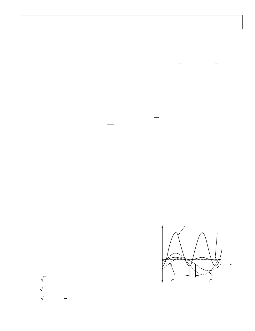
The dc component of the instantaneous reactive power signal in
each phase (A, B, and C) is then extracted by a low-pass filter to
obtain the average reactive power information on each phase.
This process is illustrated in Figure 71. The reactive power of
each phase is accumulated in the corresponding 16-bit VAR-
hour register (AVARHR, BVARHR, or CVARHR). The input to
each reactive energy register can be changed depending on the
accumulation mode setting (see Table 17).
The frequency response of the LPF in the reactive power signal
path is identical to that of the LPF2 used in the average active
power calculation (see Figure 65).
0
VRMS
×
IRMS
×
sin(
φ
)
θ
00000h
CURRENT
i(t) = 2
×
IRMS
×
sin(
ω
t)
VOLTAGE
v(t) = 2
×
VRMS
×
sin(
ω
t–
θ
)
INSTANTANEOUS
REACTIVE POWER SIGNAL
q(t) = VRMS
IRMS
sin(
φ
) + VRMS
×
IRMS
×
sin(2
ω
t+
θ
)
AVERAGE REACTIVE POWER SIGNAL =
×
IRMS
×
sin(
θ
)
Figure 71. Reactive Power Calculation
The low-pass filter is nonideal so the reactive power signal has
some ripple. This ripple is sinusoidal and has a frequency equal
相關(guān)PDF資料 |
PDF描述 |
|---|---|
| ADE7758ARW | Poly Phase Multifunction Energy Metering IC with Per Phase Information |
| ADE7758ARWRL | Poly Phase Multifunction Energy Metering IC with Per Phase Information |
| ADE7758ARWZ | Poly Phase Multifunction Energy Metering IC with Per Phase Information |
| ADE7758ARWZRL | Poly Phase Multifunction Energy Metering IC with Per Phase Information |
| ADE7759ARSRL | Active Energy Metering IC with di/dt Sensor Interface |
相關(guān)代理商/技術(shù)參數(shù) |
參數(shù)描述 |
|---|---|
| ADE7758ARW | 制造商:Analog Devices 功能描述:Energy Measurement 24-Pin SOIC W 制造商:Analog Devices 功能描述:IC ENERGY METER |
| ADE7758ARWRL | 制造商:Analog Devices 功能描述:Energy Measurement 24-Pin SOIC W T/R 制造商:Analog Devices 功能描述:IC ENERGY METER |
| ADE7758ARWZ | 功能描述:IC ENERGY METERING 3PHASE 24SOIC RoHS:是 類別:集成電路 (IC) >> PMIC - 能量測(cè)量 系列:- 產(chǎn)品培訓(xùn)模塊:Lead (SnPb) Finish for COTS Obsolescence Mitigation Program 標(biāo)準(zhǔn)包裝:2,500 系列:* |
| ADE7758ARWZ | 制造商:Analog Devices 功能描述:ENERGY METERING IC 制造商:Analog Devices 功能描述:IC, POLY-PHASE ENERGY METERING, SOIC-24 |
| ADE7758ARWZ | 制造商:Analog Devices 功能描述:IC ENERGY METER 3 PHASE SOIC-24 |
發(fā)布緊急采購(gòu),3分鐘左右您將得到回復(fù)。