- 您現在的位置:買賣IC網 > PDF目錄373980 > ADE7758 (Analog Devices, Inc.) Poly Phase Multifunction Energy Metering IC with Per Phase Information PDF資料下載
參數資料
| 型號: | ADE7758 |
| 廠商: | Analog Devices, Inc. |
| 英文描述: | Poly Phase Multifunction Energy Metering IC with Per Phase Information |
| 中文描述: | 多相多功能電能計量IC每相位信息 |
| 文件頁數: | 19/68頁 |
| 文件大小: | 1584K |
| 代理商: | ADE7758 |
第1頁第2頁第3頁第4頁第5頁第6頁第7頁第8頁第9頁第10頁第11頁第12頁第13頁第14頁第15頁第16頁第17頁第18頁當前第19頁第20頁第21頁第22頁第23頁第24頁第25頁第26頁第27頁第28頁第29頁第30頁第31頁第32頁第33頁第34頁第35頁第36頁第37頁第38頁第39頁第40頁第41頁第42頁第43頁第44頁第45頁第46頁第47頁第48頁第49頁第50頁第51頁第52頁第53頁第54頁第55頁第56頁第57頁第58頁第59頁第60頁第61頁第62頁第63頁第64頁第65頁第66頁第67頁第68頁
ADE7758
THEORY OF OPERATION
ANTIALIASING FILTER
The need for this filter is that it prevents aliasing. Aliasing is an
artifact of all sampled systems. Input signals with frequency
components higher than half the ADC sampling rate distort the
sampled signal at a frequency below half the sampling rate. This
will happen with all ADCs, regardless of the architecture. The
combination of the high sampling rate ∑- ADC used in the
ADE7758 with the relatively low bandwidth of the energy meter
allows a very simple low-pass filter (LPF) to be used as an
antialiasing filter. A simple RC filter (single pole) with a corner
frequency of 10 kHz produces an attenuation of approximately
40 dB at 833 kHz. This is usually sufficient to eliminate the
effects of aliasing.
Rev. A | Page 19 of 68
ANALOG INPUTS
The ADE7758 has a total of six analog inputs divided into two
channels: current and voltage. The current channel consists of
three pairs of fully differential voltage inputs: IAP and IAN, IBP
and IBN, and ICP and ICN. These fully differential voltage
input pairs have a maximum differential signal of ±0.5 V. The
current channel has a programmable gain amplifier (PGA) with
possible gain selection of 1, 2, or 4. In addition to the PGA, the
current channels also have a full-scale input range selection for
the ADC. The ADC analog input range selection is also made
using the gain register (see Figure 38). As mentioned previously,
the maximum differential input voltage is ±0.5 V. However, by
using Bit 3 and Bit 4 in the gain register, the maximum ADC
input voltage can be set to ±0.5 V, ±0.25 V, or ±0.125 V on the
current channels. This is achieved by adjusting the ADC
reference (see the Reference Circuit section).
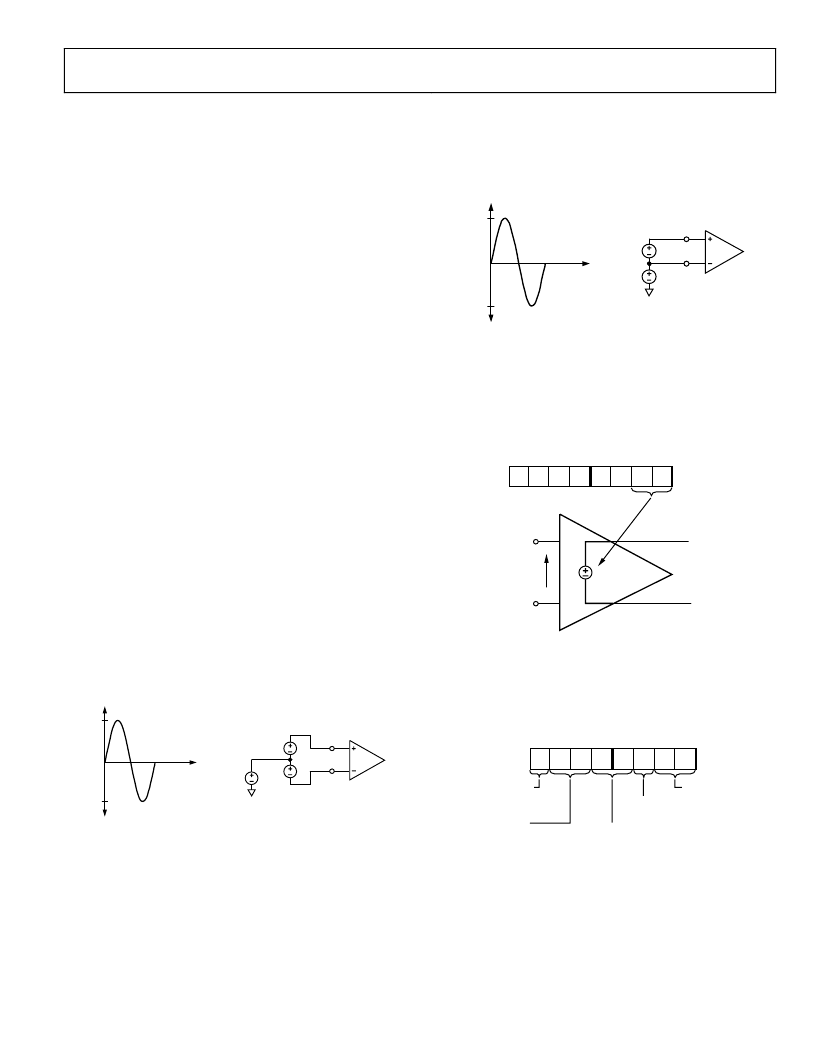
Figure 36 shows the maximum signal levels on the current
channel inputs. The maximum common-mode signal is
±25 mV as shown in Figure 36.
= 500mV MAX PEAK
V
1
+ V
2
+500mV
V
CM
V
1
IAP, IBP,
OR ICP
V
CM
–500mV
COMMON-MODE
V
1
+ V
2
V
2
IAN, IBN,
OR ICN
0
Figure 36. Maximum Signal Levels, Current Channels, Gain = 1
The voltage channel has three single-ended voltage inputs:
VAP, VBP, and VCP. These single-ended voltage inputs have a
maximum input voltage of ±0.5 V with respect to VN. Both the
current and voltage channel have a PGA with possible gain
selections of 1, 2, or 4. The same gain is applied to all the inputs
of each channel.
Figure 37 shows the maximum signal levels on the voltage
channel inputs. The maximum common-mode signal is
±25 mV as shown in Figure 36.
SINGLE-ENDED INPUT
500mV MAX PEAK
+500mV
AGND
V
CM
V2
VAP, VBP,
OR VCP
V
CM
–500mV
COMMON-MODE
25mV MAX
V
N
V2
0
Figure 37. Maximum Signal Levels, Voltage Channels, Gain = 1
The gain selections are made by writing to the gain register.
Bit 0 to Bit 1 select the gain for the PGA in the fully differential
current channel. The gain selection for the PGA in the single-
ended voltage channel is made via Bit 5 to Bit 6. Figure 38
shows how a gain selection for the current channel is made
using the gain register.
0
IAP, IBP, ICP
IAN, IBN, ICN
V
IN
K
×
V
IN
GAIN[7:0]
GAIN (K)
SELECTION
Figure 38. PGA in Current Channel
Figure 39 shows how the gain settings in PGA 1 (current
channel) and PGA 2 (voltage channel) are selected by various
bits in the gain register.
0
GAIN REGISTER*
CURRENT AND VOLTAGE CHANNEL PGA CONTROL
7 6 5 4 3 2 1 0
0 0 0 0 0 0 0 0
ADDRESS: 0x23
RESERVED
*REGISTER CONTENTS SHOW POWER-ON DEFAULTS
PGA 2 GAIN SELECT
00 =
1
01 =
×
2
10 =
×
4
INTEGRATOR ENABLE
0 = DISABLE
1 = ENABLE
PGA 1 GAIN SELECT
00 =
1
01 =
×
2
10 =
×
4
CURRENT INPUT FULL-SCALE SELECT
00 = 0.5V
01 = 0.25V
10 = 0.125V
Figure 39. ADE7758 Analog Gain Register
Bit 7 of the gain register is used to enable the digital integrator
in the current signal path. Setting this bit will activate the digital
integrator (see the di/dt Current Sensor and Digital Integrator
section).
相關PDF資料 |
PDF描述 |
|---|---|
| ADE7758ARW | Poly Phase Multifunction Energy Metering IC with Per Phase Information |
| ADE7758ARWRL | Poly Phase Multifunction Energy Metering IC with Per Phase Information |
| ADE7758ARWZ | Poly Phase Multifunction Energy Metering IC with Per Phase Information |
| ADE7758ARWZRL | Poly Phase Multifunction Energy Metering IC with Per Phase Information |
| ADE7759ARSRL | Active Energy Metering IC with di/dt Sensor Interface |
相關代理商/技術參數 |
參數描述 |
|---|---|
| ADE7758ARW | 制造商:Analog Devices 功能描述:Energy Measurement 24-Pin SOIC W 制造商:Analog Devices 功能描述:IC ENERGY METER |
| ADE7758ARWRL | 制造商:Analog Devices 功能描述:Energy Measurement 24-Pin SOIC W T/R 制造商:Analog Devices 功能描述:IC ENERGY METER |
| ADE7758ARWZ | 功能描述:IC ENERGY METERING 3PHASE 24SOIC RoHS:是 類別:集成電路 (IC) >> PMIC - 能量測量 系列:- 產品培訓模塊:Lead (SnPb) Finish for COTS Obsolescence Mitigation Program 標準包裝:2,500 系列:* |
| ADE7758ARWZ | 制造商:Analog Devices 功能描述:ENERGY METERING IC 制造商:Analog Devices 功能描述:IC, POLY-PHASE ENERGY METERING, SOIC-24 |
| ADE7758ARWZ | 制造商:Analog Devices 功能描述:IC ENERGY METER 3 PHASE SOIC-24 |
發(fā)布緊急采購,3分鐘左右您將得到回復。