- 您現(xiàn)在的位置:買賣IC網(wǎng) > PDF目錄373980 > ADE7754ARRL (ANALOG DEVICES INC) ADE7754 PDF資料下載
參數(shù)資料
| 型號: | ADE7754ARRL |
| 廠商: | ANALOG DEVICES INC |
| 元件分類: | 模擬信號調(diào)理 |
| 英文描述: | ADE7754 |
| 中文描述: | SPECIALTY ANALOG CIRCUIT, PDSO24 |
| 封裝: | MS-013AD, SOIC-24 |
| 文件頁數(shù): | 21/44頁 |
| 文件大小: | 630K |
| 代理商: | ADE7754ARRL |
第1頁第2頁第3頁第4頁第5頁第6頁第7頁第8頁第9頁第10頁第11頁第12頁第13頁第14頁第15頁第16頁第17頁第18頁第19頁第20頁當(dāng)前第21頁第22頁第23頁第24頁第25頁第26頁第27頁第28頁第29頁第30頁第31頁第32頁第33頁第34頁第35頁第36頁第37頁第38頁第39頁第40頁第41頁第42頁第43頁第44頁
REV. PrG 01/03
PRELIMINARY TECHNICAL DATA
ADE7754
–
21
–
Reverse Power Information
The ADE7754 detects when the current and voltage channels
of any of the three phase inputs have a phase difference greater
than 90° i.e.
|Φ
A
| or
|Φ
B
| or
|Φ
C
| > 90°. This mechanism can
detect wrong connection of the meter or generation of Active
Energy.
The Reverse power information is available for Phase A - B
and C respectively by reading bit12-14 of the CFNUM
register - see Table XI. The state of these bits represent the
sign of the active power of the corresponding phase. Logic
one corresponds to negative active power.
The AENERGY phase selection bits (WATSEL bits of the
WATMode register) enable the negative power detection per
phase. If Phase A is enabled in the AENERGY accumulation
-bit 5 of WATMode register sets to logic one- the negative
power detection for Phase A -bit 12 of CFNUM register-
indicates the direction of the active energy. If Phase A is
disabled in the AENERGY register, the negative power bit
for Phase A is set to logic zero.
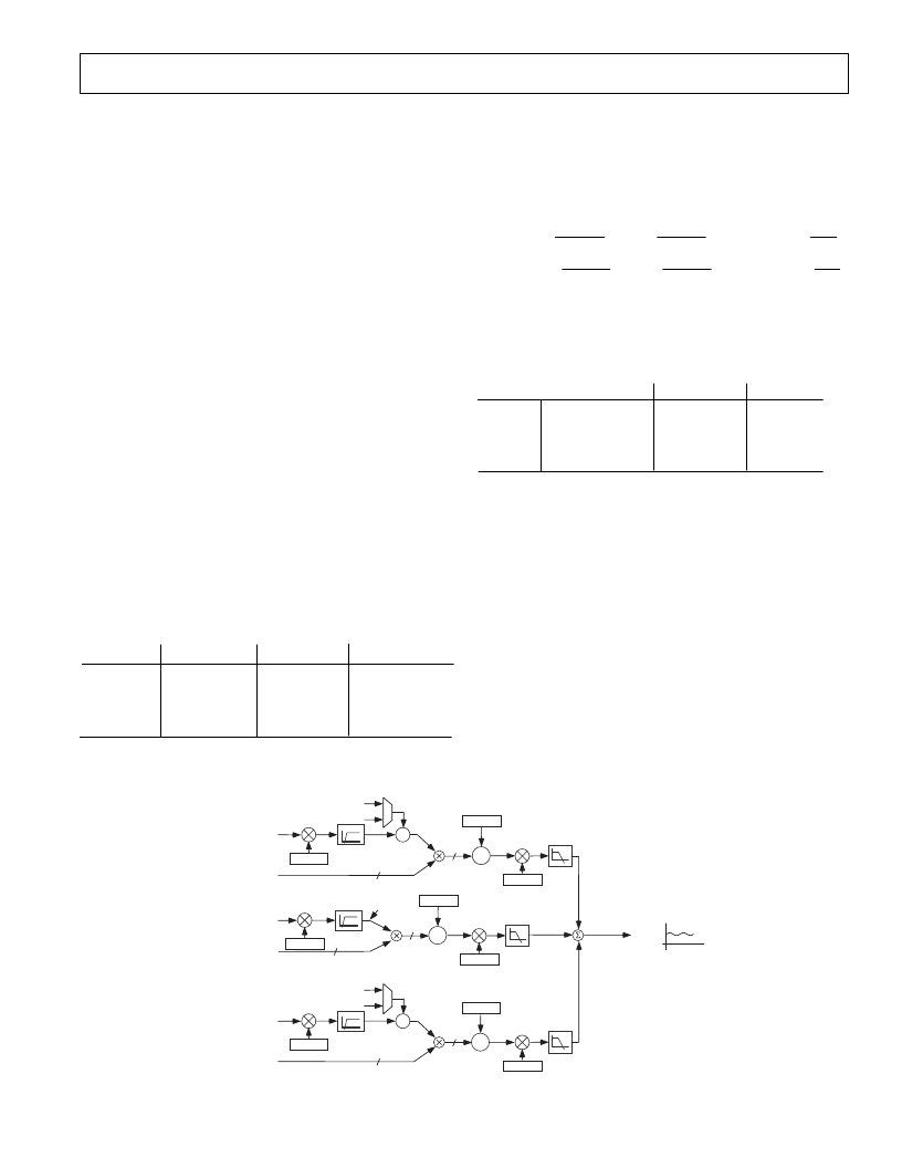
TOTAL ACTIVE POWER CALCULATION
The sum of the active powers coming from each phase gives
the total active Power consumption. Different combinations
of the three phases can be selected in the sum by setting bits
7-6 of the WATMode register (mnemonic WATMOD[1:0]).
Figure 24 demonstrates the calculation of the total active
power.
The total active power calculated by the ADE7754 depends
on the configuration of the WATMOD bits in the WATMode
register. Each term of the formula can be disabled or enabled
by setting WATSEL bits respectively to logic 0 or logic 1 in
the WATMode register. The different configurations are
described in Table I.
WATMOD
WATSEL0
WATSEL1
0d
V
A
x I
A*
+ V
B
x I
B*
1d
V
A
x (I
A*
-I
B*
) + 0
2d
V
A
x (I
A*
-I
B*
) + 0
WATSEL2
+ V
C
x I
C*
+ V
C
x (I
C*
-I
B*
)
+ V
C
x I
C*
Table I - Total Active Power calculation
Note: I
A*
, I
B*
and I
C*
represent the current channels samples
after APGAIN correction and High-Pass Filtering.
For example, for WATMOD = 1, when all the gains and
offsets corrections are taken into consideration, the exact
formula that is used to process the Active Power is:
Total Active Power
V
AAPGAIN
2
I
BAPGAIN
2
A
A
=
+
+
1
1
12
12
+
+
+
I
AAPOS
AWG
2
V
CAPGAIN
2
B
C
1
1
12
12
+
+
I
BAPGAIN
2
I
CAPOS
CWG
2
C
B
1
1
12
12
Depending on the polyphase meter service, the appropriate
formula should be chosen to calculate the Active power. The
American ANSI C12.10 standard defines the different con-
figurations of the meter. Table II describes which mode
should be chosen in these different configurations.
ANSI Meter Form
WATMOD
5S/13S
3-wire Delta
0
6S/14S
4-wire Wye
1
8S/15S
4-wire Delta
2
9S/16S
4-wire Wye
0
WATSEL
3 or 5 or 6
5
5
7
Table II - Meter form configuration
Different gain calibration parameters are offered in the
ADE7754 to cover the calibration of the meter in different
configurations. It should be noticed that in Mode 0, APGAIN
and WGAIN registers have the same effect on the end result.
In this case, APGAIN registers should be set at their default
value and the gain adjustment should be done with the
WGAIN registers.
I
A
V
A
PHASE A*
1
28
LPF2
HPF
BAPGAIN
BWGAIN
I
B*
Total Instantaneous
Power Signal
Active Power
Signal - P
2752545h
I
B
V
B
PHASE B*
1
HPF
28
LPF2
CAPGAIN
CWGAIN
S
+
-
0
I
B*
I
C
V
C
PHASE C*
1
HPF
28
LPF2
AAPGAIN
AWGAIN
S
+
-
0
I
B*
S
+
AAPOS
S
+
BAPOS
S
+
CAPOS
Figure 24 –Total Active Power Consumption Calculation
相關(guān)PDF資料 |
PDF描述 |
|---|---|
| ADE7755AN-REF | Energy Metering IC with Pulse Output |
| ADE7755ARSRL | Energy Metering IC with Pulse Output |
| ADE7755 | Energy Metering IC with Pulse Output |
| ADE7755ARS | Energy Metering IC with Pulse Output |
| ADE7756EB | Evaluation Board Documentation AD7756 Energy metering IC |
相關(guān)代理商/技術(shù)參數(shù) |
參數(shù)描述 |
|---|---|
| ADE7754ARZ | 功能描述:IC ENERGY METERING 3PHASE 24SOIC RoHS:是 類別:集成電路 (IC) >> PMIC - 能量測量 系列:- 產(chǎn)品培訓(xùn)模塊:Lead (SnPb) Finish for COTS Obsolescence Mitigation Program 標(biāo)準(zhǔn)包裝:2,500 系列:* |
| ADE7754ARZRL | 功能描述:IC ENERGY METERING 3PHASE 24SOIC RoHS:是 類別:集成電路 (IC) >> PMIC - 能量測量 系列:- 產(chǎn)品培訓(xùn)模塊:Lead (SnPb) Finish for COTS Obsolescence Mitigation Program 標(biāo)準(zhǔn)包裝:2,500 系列:* |
| ADE7755 | 制造商:AD 制造商全稱:Analog Devices 功能描述:Energy Metering IC with Pulse Output |
| ADE7755AARSRL | 制造商:Analog Devices 功能描述:ENERGY METERING IC WITH P - Tape and Reel |
| ADE7755AN | 制造商:Rochester Electronics LLC 功能描述: 制造商:Analog Devices 功能描述: |
發(fā)布緊急采購,3分鐘左右您將得到回復(fù)。