- 您現(xiàn)在的位置:買賣IC網(wǎng) > PDF目錄375238 > AD7750AN (ANALOG DEVICES INC) Product-to-Frequency Converter PDF資料下載
參數(shù)資料
| 型號(hào): | AD7750AN |
| 廠商: | ANALOG DEVICES INC |
| 元件分類: | 模擬信號(hào)調(diào)理 |
| 英文描述: | Product-to-Frequency Converter |
| 中文描述: | SPECIALTY ANALOG CIRCUIT, PDIP20 |
| 封裝: | PLASTIC, DIP-20 |
| 文件頁(yè)數(shù): | 1/16頁(yè) |
| 文件大小: | 195K |
| 代理商: | AD7750AN |
當(dāng)前第1頁(yè)第2頁(yè)第3頁(yè)第4頁(yè)第5頁(yè)第6頁(yè)第7頁(yè)第8頁(yè)第9頁(yè)第10頁(yè)第11頁(yè)第12頁(yè)第13頁(yè)第14頁(yè)第15頁(yè)第16頁(yè)
REV. 0
Information furnished by Analog Devices is believed to be accurate and
reliable. However, no responsibility is assumed by Analog Devices for its
use, nor for any infringements of patents or other rights of third parties
which may result from its use. No license is granted by implication or
otherwise under any patent or patent rights of Analog Devices.
a
AD7750
One Technology Way, P.O. Box 9106, Norwood, MA 02062-9106, U.S.A.
Tel: 781/329-4700
World Wide Web Site: http://www.analog.com
Fax: 781/326-8703
Analog Devices, Inc., 1997
Product-to-Frequency
Converter
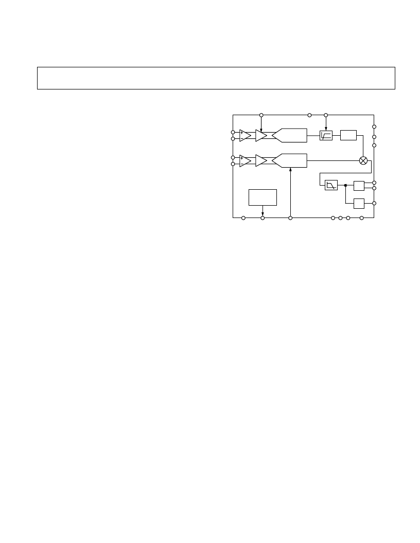
FUNCT IONAL BLOCK DIAGRAM
DELAY
2.5V
BAND GAP
REFERENCE
DTF
HPF
MULT
S1
FS
VDD
DGND
DTF
LPF
2ND ORDER
MODULATOR
AGND
REFOUT
G1
ADC1
ADC2
REFIN
V
1+
V
1–
AD7750
2ND ORDER
MODULATOR
x2
x16
V
2+
V
2–
S2
F2
CLKOUT
F1
F
OUT
REVP
CLKIN
ACDC
FEATURES
Two Differential Analog Input Channels
Product of Two Channels
Voltage-to-Frequency Conversion on a Single Channel
Real Power Measurement Capability
< 0.2% Error Over the Range 400% Ibasic to 2% Ibasic
Two or Four Quadrant Operation (Positive and
Negative Power)
Gain Select of 1 or 16 on the Current Channel (Channel 1)
Choice of On-Chip or External Reference
Choice of Output Pulse Frequencies Available
(Pins F1 and F2)
High Frequency Pulse Output for Calibration Purposes
(F
OUT
)
HPF on Current Channel for Offset Removal
Single 5 V Supply and Low Power
GE NE RAL DE SCRIPT ION
T he AD7750 is a Product-to-Frequency Converter (PFC)
that can be configured for power measurement or voltage-to-
frequency conversion. T he part contains the equivalent of two
channels of A/D conversion, a multiplier, a digital-to-frequency
converter, a reference and other conditioning circuitry. Channel 1
has a differential gain amplifier with selectable gains of 1 or 16.
Channel 2 has a differential gain amplifier with a gain of 2. A high-
pass filter can be switched into the signal path of Channel 1 to
remove any offsets.
T he outputs F1 and F2 are fixed width (275 ms) logic low going
pulse streams for output frequencies less than 1.8 Hz. A range
of output frequencies is available and the frequency of F1 and
F2 is proportional to the product of V
1
and V
2
. T hese outputs
are suitable for directly driving an electromechanical pulse
counter or full stepping two phase stepper motors. T he outputs
can be configured to represent the result of four-quadrant multi-
plication (i.e., Sign and Magnitude) or to represent the result of
a two quadrant multiplication (i.e., Magnitude Only). In this
configuration the outputs are always positive regardless of the
input polarities. In addition, there is a reverse polarity indicator
output that becomes active when negative power is detected in
the Magnitude Only Mode, see Reverse Polarity Indicator.
T he error as a percent (%) of reading is less than 0.3% over a
dynamic range of 1000:1.
T he AD7750 is fabricated on 0.6
μ
CMOS technology; a pro-
cess that combines low power and low cost.
PRODUCT HIGHLIGHT S
1. T he part can be configured for power measurement or
voltage-to-frequency conversion.
2. T he output format and maximum frequency is selectable;
from low-frequency outputs, suitable for driving stepper
motors, to higher frequency outputs, suitable for calibration
and test.
3. T here is a reverse polarity indicator output that becomes
active when negative power is detected in the Magnitude
Only Mode.
4. Error as a % of reading over a dynamic range of 1000:1 is
< 0.3%.
相關(guān)PDF資料 |
PDF描述 |
|---|---|
| AD7750AR | Product-to-Frequency Converter |
| AD7751(中文) | Energy Metering IC with On-Chip Fault Detection(高精度容錯(cuò)電子能量測(cè)量芯片) |
| AD7751 | Energy Metering IC with On-Chip Fault Detection(高精度容錯(cuò)電子能量測(cè)量芯片) |
| AD7755(中文) | Energy Metering IC with Pulse Output(帶脈沖輸出的高精度電子能量測(cè)量芯片) |
| AD7755 | Energy Metering IC with Pulse Output(帶脈沖輸出的高精度電子能量測(cè)量芯片) |
相關(guān)代理商/技術(shù)參數(shù) |
參數(shù)描述 |
|---|---|
| AD7750AN | 制造商:Analog Devices 功能描述:SEMICONDUCTOR ((NW)) |
| AD7750AR | 制造商:Rochester Electronics LLC 功能描述:PRODUCT TO FREQUENCY CONVERTER I.C. - Bulk |
| AD7750AR-REEL | 制造商:Analog Devices 功能描述: |
| AD7751 | 制造商:AD 制造商全稱:Analog Devices 功能描述:Energy Metering IC With On-Chip Fault Detection |
| AD7751AAN | 制造商:Analog Devices 功能描述: 制造商:Rochester Electronics LLC 功能描述:PRODUCT TO FREQUENCY CONV - Bulk |
發(fā)布緊急采購(gòu),3分鐘左右您將得到回復(fù)。