- 您現(xiàn)在的位置:買賣IC網(wǎng) > PDF目錄24828 > 935268625518 (NXP SEMICONDUCTORS) UNIVERSAL SERIAL BUS CONTROLLER, PQFP64 PDF資料下載
參數(shù)資料
| 型號: | 935268625518 |
| 廠商: | NXP SEMICONDUCTORS |
| 元件分類: | 總線控制器 |
| 英文描述: | UNIVERSAL SERIAL BUS CONTROLLER, PQFP64 |
| 封裝: | 10 X 10 MM, 1.40 MM HEIGHT, PLASTIC, MS-026, SOT-314-2, LQFP-64 |
| 文件頁數(shù): | 10/82頁 |
| 文件大小: | 1965K |
| 代理商: | 935268625518 |
第1頁第2頁第3頁第4頁第5頁第6頁第7頁第8頁第9頁當(dāng)前第10頁第11頁第12頁第13頁第14頁第15頁第16頁第17頁第18頁第19頁第20頁第21頁第22頁第23頁第24頁第25頁第26頁第27頁第28頁第29頁第30頁第31頁第32頁第33頁第34頁第35頁第36頁第37頁第38頁第39頁第40頁第41頁第42頁第43頁第44頁第45頁第46頁第47頁第48頁第49頁第50頁第51頁第52頁第53頁第54頁第55頁第56頁第57頁第58頁第59頁第60頁第61頁第62頁第63頁第64頁第65頁第66頁第67頁第68頁第69頁第70頁第71頁第72頁第73頁第74頁第75頁第76頁第77頁第78頁第79頁第80頁第81頁第82頁
Philips Semiconductors
ISP1581
Hi-Speed USB interface device
Product data
Rev. 05 — 26 February 2003
18 of 78
9397 750 10766
Koninklijke Philips Electronics N.V. 2003. All rights reserved.
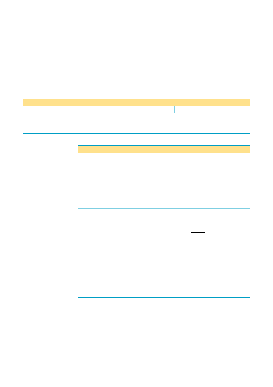
9.2.2
Mode register (address: 0CH)
This register consists of 1 byte (bit allocation: see Table 7). In 16-bit bus mode the
upper byte is ignored.
The Mode register controls the resume, suspend and wake-up behavior, interrupt
activity, soft reset, clock signals and SoftConnect operation.
9.2.3
Interrupt Conguration register (address: 10H)
This 1-byte register determines the behavior and polarity of the INT output. The bit
allocation is shown in Table 9. When the USB SIE receives or generates a ACK, NAK
or STALL, it will generate interrupts depending on three Debug mode bit elds:
CDBGMOD[1:0]: interrupts for the Control endpoint 0
DDBGMODIN[1:0]: interrupts for the DATA IN endpoints 1 to 7
Table 7:
Mode register: bit allocation
Bit
7
6
5
4
3
2
1
0
Symbol
CLKAON
SNDRSU
GOSUSP
SFRESET
GLINTENA
WKUPCS
reserved
SOFTCT
Reset
0
0000
-
0
Bus reset
0
unchanged
0
-
unchanged
Access
R/W
-
R/W
Table 8:
Mode register: bit description
Bit
Symbol
Description
7
CLKAON
Clock Always On: A logic 1 indicates that the internal clocks
are always running even during ‘suspend’ state. A logic 0
switches off the internal oscillator and PLL, when they are not
needed. During ‘suspend’ state, this bit must be set to logic 0 to
meet the suspend current requirements. The clock is stopped
after a delay of approximately 2 ms, following the setting of bit
GOSUSP.
6
SNDRSU
Send Resume: Writing a logic 1 followed by a logic 0 will
generate an upstream ‘resume’ signal of 10 ms duration, after a
5 ms delay.
5
GOSUSP
Go Suspend: Writing a logic 1 followed by a logic 0 will activate
‘suspend’ mode.
4
SFRESET
Soft Reset: Writing a logic 1 followed by a logic 0 will enable a
software-initiated reset to ISP1581. A soft reset is similar to a
hardware-initiated reset (via the RESET pin).
3
GLINTENA
Global Interrupt Enable: A logic 1 enables all interrupts.
Individual interrupts can be masked OFF by clearing the
corresponding bits in the Interrupt Enable register. Bus reset
value: unchanged.
2
WKUPCS
Wake-up on Chip Select: A logic 1 enables remote wake-up
via a LOW level on input CS.
1
-
reserved; must write logic 0
0
SOFTCT
SoftConnect: A logic 1 enables the connection of the 1.5 k
pull-up resistor on pin RPU to the D
+ line. Bus reset value:
unchanged.
相關(guān)PDF資料 |
PDF描述 |
|---|---|
| 935268625551 | UNIVERSAL SERIAL BUS CONTROLLER, PQFP64 |
| 080207R0 | TELEFON-AKKU |
| 080216R0 | TELEFON-AKKU |
| 080219R0 | TELEFON-AKKU |
| 080251R0 | TELEFON-AKKU |
相關(guān)代理商/技術(shù)參數(shù) |
參數(shù)描述 |
|---|---|
| 935268721125 | 制造商:NXP Semiconductors 功能描述:Buffer/Line Driver 1-CH Non-Inverting 3-ST CMOS 5-Pin TSSOP T/R |
| 935269304128 | 制造商:ST-Ericsson 功能描述:IC AUDIO CODEC W/TCH SCRN 48LQFP |
| 935269544557 | 制造商:NXP Semiconductors 功能描述:SUB ONLY TDA9587-2US1-V1.3 |
| 935269987557 | 制造商:NXP Semiconductors 功能描述:SUB ONLY TDA9587-1US1-V1.8 SUBBED TO 935269987557 |
| 935270713557 | 制造商:NXP Semiconductors 功能描述:SUB ONLY IC CHP |
發(fā)布緊急采購,3分鐘左右您將得到回復(fù)。