- 您現(xiàn)在的位置:買賣IC網(wǎng) > PDF目錄2021 > 14242 (Desco)TOOL MICASTAT FLUSH MNT INSERT PDF資料下載
參數(shù)資料
| 型號: | 14242 |
| 廠商: | Desco |
| 文件頁數(shù): | 6/8頁 |
| 文件大?。?/td> | 0K |
| 描述: | TOOL MICASTAT FLUSH MNT INSERT |
| 標準包裝: | 1 |
| 附件類型: | 安裝工具 |
| 適用于相關(guān)產(chǎn)品: | 嵌入安裝 |

TB-2091 Page 6 of 8
performing this test on Micastat
Pads the snap serves as
the ground point.
A second type of test is RTT (Resistance, Point to Point).
Here you measure the resistance from one 5 lb. electrode
to another 5 lb. electrode; see electrode test positions A, B,
C, and D in RTT test diagram, Figure 13. This is the test
that is more typically used in the laboratory to determine
Micastat
compliance with electrical specifications.
Both test procedures are outlined in this Technical Bulletin
using the Desco Surface Resistance Test Kit Item No.
19780.
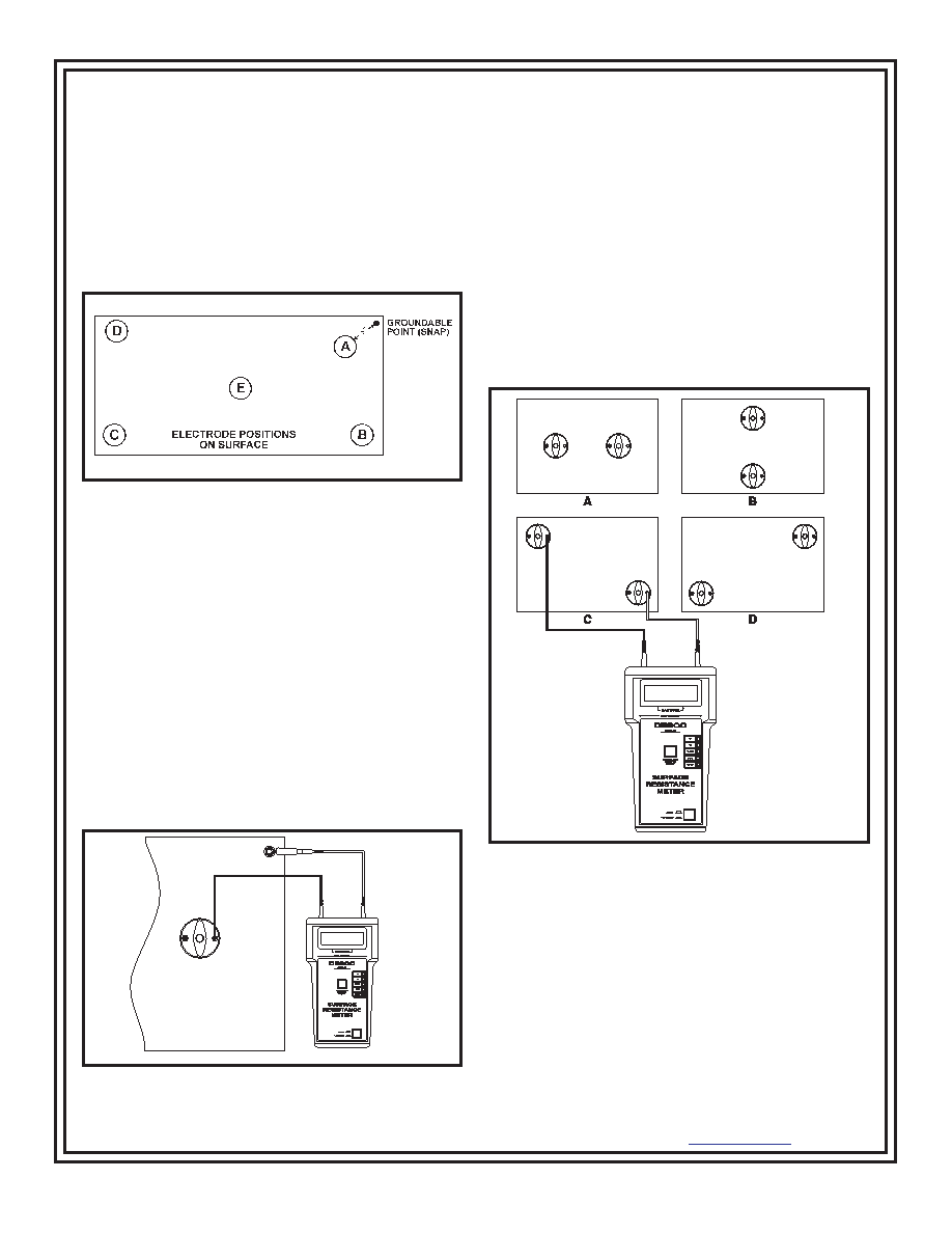
Figure 11. Electrode positions on surface of pad, RTG test.
Resistance To Ground (RTG):
1. Locate the five pound electrode positions, as described
below, to be used on the Micastat
surface in relationship
to the installed ground bolt (or snap on the Micastat
Pad). Use the relative positions shown above.
A -
At least 2" from any surface edge and 3"
from the ground bolt.
B, C & D - The farthest corners from the ground bolt and
2" from any surface edge.
E -
The geometric center of the surface.
2. Disconnect the surface to be tested from its normal
ground connection.
3. Connect one black lead to the meter and the other end
of this lead to the 5 lb. electrode.
Figure 12. Proper connection of leads.
4. Connect the other black lead to the meter and the
groundable point on the mat.
5. Place the electrode at position A on the mat (see the
RTG diagram) and set the meter selector switch to 100V.
6. Push on On/Off button, for the 15 second electrification
period and then record the reading in ohms.
7. Release the On/Off button. Move the electrode to each
of the other four positions on the surface and repeat the
test.
8. Average the results of the five readings to obtain an
average measurement of the resistance of surface to
ground.
Resistance Point to Point (RTT):
Figure 13. Electrode positions on surface of pad, RTT test.
1. Locate the four pair of electrode positions to be used
approximately as shown in the RTT test diagram above.
Position electrodes at least 10 inches apart and not less
than two inches from any edge.
2. Disconnect the surface to be tested from its normal
ground connection.
3. Connect one end of the black lead to the meter connect
the other end of this lead to either one of the electrodes.
It does not matter which lead is connected to which
weighted electrode.
DESCO WEST - 3651 Walnut Avenue, Chino, CA 91710 (909) 627-8178 Fax (909) 627-7449
DESCO EAST - One Colgate Way, Canton, MA 02021-1407 (781) 821-8370 Fax (781) 575-0172 Web Site: http://www.desco.com
2009 DESCO INDUSTRIES, INC.
Employee Owned
相關(guān)PDF資料 |
PDF描述 |
|---|---|
| 14401 | WRIST STRAP VINYL DISPOSABLE |
| 14404 | WRIST STRAP DISPOSABLE |
| 14830 | WRIST STRAP ELASTIC W/10' CORD |
| 1501824 | STATIC BAG MET-OUT 18"X24" 100PK |
| 16006X | VINYL DISS BRN VGRV .125 48X40' |
相關(guān)代理商/技術(shù)參數(shù) |
參數(shù)描述 |
|---|---|
| 1424-2 | 功能描述:電路板硬件 - PCB .082 Swage micro pin Tin RoHS:否 制造商:Harwin 類型:Shield Clip 長度:9.4 mm 螺紋大小: 外徑: 材料:Beryllium Copper 電鍍:Tin |
| 14242/000 | 制造商:未知廠家 制造商全稱:未知廠家 功能描述:CIRCUIT BOARD FOR PCB PSU'S |
| 1424200 | 功能描述:SENSOR/ACTUATOR FLUSH-TYPE PLG 1 制造商:phoenix contact 系列:* 零件狀態(tài):在售 標準包裝:20 |
| 14242-000 | 制造商:VXI POWER 功能描述:PCB FOR VXI 5W PSUS |
| 1424201 | 功能描述:SENSOR/ACTUATOR FLUSH-TYPE SOCKE 制造商:phoenix contact 系列:* 零件狀態(tài):在售 標準包裝:20 |
發(fā)布緊急采購,3分鐘左右您將得到回復(fù)。