- 您現(xiàn)在的位置:買賣IC網(wǎng) > PDF目錄372941 > XR16C850IM UART|CMOS|TQFP|48PIN|PLASTIC PDF資料下載
參數(shù)資料
| 型號(hào): | XR16C850IM |
| 英文描述: | UART|CMOS|TQFP|48PIN|PLASTIC |
| 中文描述: | 異步|的CMOS | TQFP封裝| 48PIN |塑料 |
| 文件頁(yè)數(shù): | 6/49頁(yè) |
| 文件大小: | 690K |
| 代理商: | XR16C850IM |
第1頁(yè)第2頁(yè)第3頁(yè)第4頁(yè)第5頁(yè)當(dāng)前第6頁(yè)第7頁(yè)第8頁(yè)第9頁(yè)第10頁(yè)第11頁(yè)第12頁(yè)第13頁(yè)第14頁(yè)第15頁(yè)第16頁(yè)第17頁(yè)第18頁(yè)第19頁(yè)第20頁(yè)第21頁(yè)第22頁(yè)第23頁(yè)第24頁(yè)第25頁(yè)第26頁(yè)第27頁(yè)第28頁(yè)第29頁(yè)第30頁(yè)第31頁(yè)第32頁(yè)第33頁(yè)第34頁(yè)第35頁(yè)第36頁(yè)第37頁(yè)第38頁(yè)第39頁(yè)第40頁(yè)第41頁(yè)第42頁(yè)第43頁(yè)第44頁(yè)第45頁(yè)第46頁(yè)第47頁(yè)第48頁(yè)第49頁(yè)
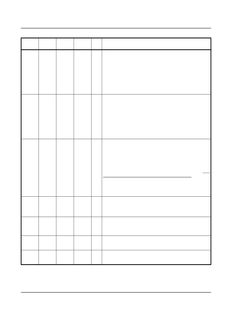
XR16C854/XR16C854D
3.3V AND 5V QUAD UART WITH 128-BYTE FIFO
REV. 2.0
á
6
INTA
(IRQ#)
6
15
12
O
(OD)
When 16/68# pin is at logic 1 for Intel bus interface, this ouput
becomes channel A interrupt output. The output state is defined by
the user and through the software setting of MCR[3]. INTA is set to
the active mode when MCR[3] is set to a logic 1. INTA is set to the
three state mode when MCR[3] is set to a logic 0 (default). See
MCR[3].
When 16/68# pin is at logic 0 for Motorola bus interface, this output
becomes device interrupt output (active low, open drain). An external
pull-up resistor is required for proper operation.
Motorola bus interface is not available on the 64 pin package.
When 16/68# pin is at logic 1 for Intel bus interface, these ouputs
become the interrupt outputs for channels B, C, and D. The output
state is defined by the user through the software setting of MCR[3].
The interrupt outputs are set to the active mode when MCR[3] is set
to a logic 1 and are set to the three state mode when MCR[3] is set to
a logic 0 (default). See MCR[3].
When 16/68# pin is at logic 0 for Motorola bus interface, these out-
puts are unused and will stay at logic zero level. Leave these outputs
unconnected.
Motorola bus interface is not available on the 64 pin package.
Interrupt Select (active high, input with internal pull-down).
When 16/68# pin is at logic 1 for Intel bus interface, this pin can be
used in conjunction with MCR bit-3 to enable or disable the INT A-D
pins or override MCR bit-3 and enable the interrupt outputs. Interrupt
outputs are enabled continuously by making this pin a logic 1. Mak-
ing this pin a logic 0 allows MCR bit-3 to enable and disable the inter-
rupt output pins. In this mode, MCR bit-3 is set to a logic 1 to enable
the continuous output. See MCR bit-3 description for full detail. This
pin must be at logic 0 in the Motorola bus interface mode. Due to pin
limitations on 64 pin packages, this pin is not available. To cover this
limitation, two 64 pin TQFP packages versions are offered. The
XR16C854D operates in the continuous interrupt enable mode by
bonding this pin to VCC internally.
UART channels A-D Transmitter Ready (active low). The out-
puts provide the TX FIFO/THR status for transmit channels A-
D. See Table 5 . If these outputs are unused, leave them un-
connected.
INTB
INTC
INTD
(N.C.)
12
37
43
21
49
55
18
63
69
O
INTSEL
-
65
87
I
TXRDYA#
TXRDYB#
TXRDYC#
TXRDYD#
-
-
-
-
-
-
-
-
5
25
56
81
O
RXRDYA#
RXRDYB#
RXRDYC#
RXRDYD#
TXRDY#
-
-
-
-
-
-
-
-
-
100
31
50
82
45
O
UART channels A-D Receiver Ready (active low). This output pro-
vides the RX FIFO/RHR status for receive channels A-D. See Table 5
. If these outputs are unused, leave them unconnected.
39
O
Transmitter Ready (active low). This output is a logically wire-ORed
status of TXRDY# A-D. See Table 5 . If this output is unused, leave
it unconnected.
Receiver Ready (active low). This output is a logically wire-ORed sta-
tus of RXRDY# A-D. See Table 5 . If this output is unused, leave it
unconnected.
RXRDY#
-
38
44
O
Pin Description
N
AME
64-TQFP
P
IN
#
68-PLCC
P
IN
#
100-QFP
P
IN
#
T
YPE
D
ESCRIPTION
相關(guān)PDF資料 |
PDF描述 |
|---|---|
| XR16C850IP | UART|CMOS|DIP|40PIN|PLASTIC |
| XR16C850IQ | UART|CMOS|QFP|52PIN|PLASTIC |
| XR17C158CV | UART |
| XR17C158IV | UART |
| XR215CP | IC-PHASE LOCKED LOOP |
相關(guān)代理商/技術(shù)參數(shù) |
參數(shù)描述 |
|---|---|
| XR16C850IM-F | 功能描述:UART 接口集成電路 UARTW/128BYTE FIFO RoHS:否 制造商:Texas Instruments 通道數(shù)量:2 數(shù)據(jù)速率:3 Mbps 電源電壓-最大:3.6 V 電源電壓-最小:2.7 V 電源電流:20 mA 最大工作溫度:+ 85 C 最小工作溫度:- 40 C 封裝 / 箱體:LQFP-48 封裝:Reel |
| XR16C850IMTR-F | 功能描述:UART 接口集成電路 UART W/128 BYTE FIFO RoHS:否 制造商:Texas Instruments 通道數(shù)量:2 數(shù)據(jù)速率:3 Mbps 電源電壓-最大:3.6 V 電源電壓-最小:2.7 V 電源電流:20 mA 最大工作溫度:+ 85 C 最小工作溫度:- 40 C 封裝 / 箱體:LQFP-48 封裝:Reel |
| XR16C850IP | 制造商:未知廠家 制造商全稱:未知廠家 功能描述:UART|CMOS|DIP|40PIN|PLASTIC |
| XR16C850IQ | 制造商:未知廠家 制造商全稱:未知廠家 功能描述:UART|CMOS|QFP|52PIN|PLASTIC |
| XR16C854 | 制造商:EXAR 制造商全稱:EXAR 功能描述:并轉(zhuǎn)串4串口擴(kuò)展芯片 |
發(fā)布緊急采購(gòu),3分鐘左右您將得到回復(fù)。