- 您現(xiàn)在的位置:買賣IC網(wǎng) > PDF目錄372881 > XCR3320-8TQ144I PDF資料下載
參數(shù)資料
| 型號(hào): | XCR3320-8TQ144I |
| 文件頁(yè)數(shù): | 14/43頁(yè) |
| 文件大小: | 396K |
| 代理商: | XCR3320-8TQ144I |
第1頁(yè)第2頁(yè)第3頁(yè)第4頁(yè)第5頁(yè)第6頁(yè)第7頁(yè)第8頁(yè)第9頁(yè)第10頁(yè)第11頁(yè)第12頁(yè)第13頁(yè)當(dāng)前第14頁(yè)第15頁(yè)第16頁(yè)第17頁(yè)第18頁(yè)第19頁(yè)第20頁(yè)第21頁(yè)第22頁(yè)第23頁(yè)第24頁(yè)第25頁(yè)第26頁(yè)第27頁(yè)第28頁(yè)第29頁(yè)第30頁(yè)第31頁(yè)第32頁(yè)第33頁(yè)第34頁(yè)第35頁(yè)第36頁(yè)第37頁(yè)第38頁(yè)第39頁(yè)第40頁(yè)第41頁(yè)第42頁(yè)第43頁(yè)
14
Configuration Data Format
Overview
The XCR3320 functionality is determined by the state of
internal configuration RAM. This section discusses the con-
figuration data format, and the function of each field in con-
figuration data packets.
Configuration Data Packets
Configuration of the XCR3320 is done using configuration
packets. The configuration packet is shown in
Figure 11
.
The data packet consists of a header and a data frame.
There are four types of data frames. The header is shifted
into the device first, followed by one data frame. Configura-
tion of a single XCR3320 requires 338 data packets, one for
each address. All preceding data must contain only 1
’
s.
Once a device is configured, it retransmits data of any
polarity. Before and during configuration, all data retrans-
mitted out the daisy-chain port (dout) are 1
’
s.
The ordering of the data packets may be random, but they
cannot be mixed with other devices
’
data packets. Align-
ment bits are not required between data packets. If used,
alignment bits must be included in the length count, and
they must be at least 2-bits long.
The header is fixed and consists of five fields:
Leading 1s,
Preamble,
CRC Enable,
CRC Bits,
Compression Bits.
The leading 1s enter the device first. The following is a
description of each field in the header.
Leading 1s:
This is a four or greater bit field consisting of 1s.
Preamble/Postamble:
This is a four bit field which indicates the start of a
frame or the end of configuration:
Preamble: -0010 - signals the beginning of a config-
uration data packet.
Postamble: 0100 -signals the end of configuration.
All other values of the preamble field force configu-
ration of the entire system to restart.
The segments CRC Enable, CRC Bits, and Compression
Bits are valid only if the Preamble field is 0010.
Cyclic Redundancy Check (CRC) Enable:
In this single bit field, a 0 disables CRC checking of
the data stream. If the CRC is disabled the 16 bit
CRC field must be the default described below. A1
enables CRC error checking of the data stream.
CRC Error Checking:
The CRC field is a 16 bit field. The default value is
1010_1010_1010_1010. The calculated value is
from data, address, stop bit, and first alignment bit
(starting with crc_reg[15:0] = [0]). Using verilog
operators, the crc is calculated as:
crc_reg[14:2] <= cr_reg[14:2] << 1;
cr_reg[2] <= cr_reg[15]^din^cr_reg[1];
cr_reg[1] <= cr_reg[0];
cr_reg[0] < cr_reg[15]^din;
cr_reg[15] <= cr_reg[15]^din^cr_reg[14];
If a CRC error is detected, configuration is halted
and must be restarted.
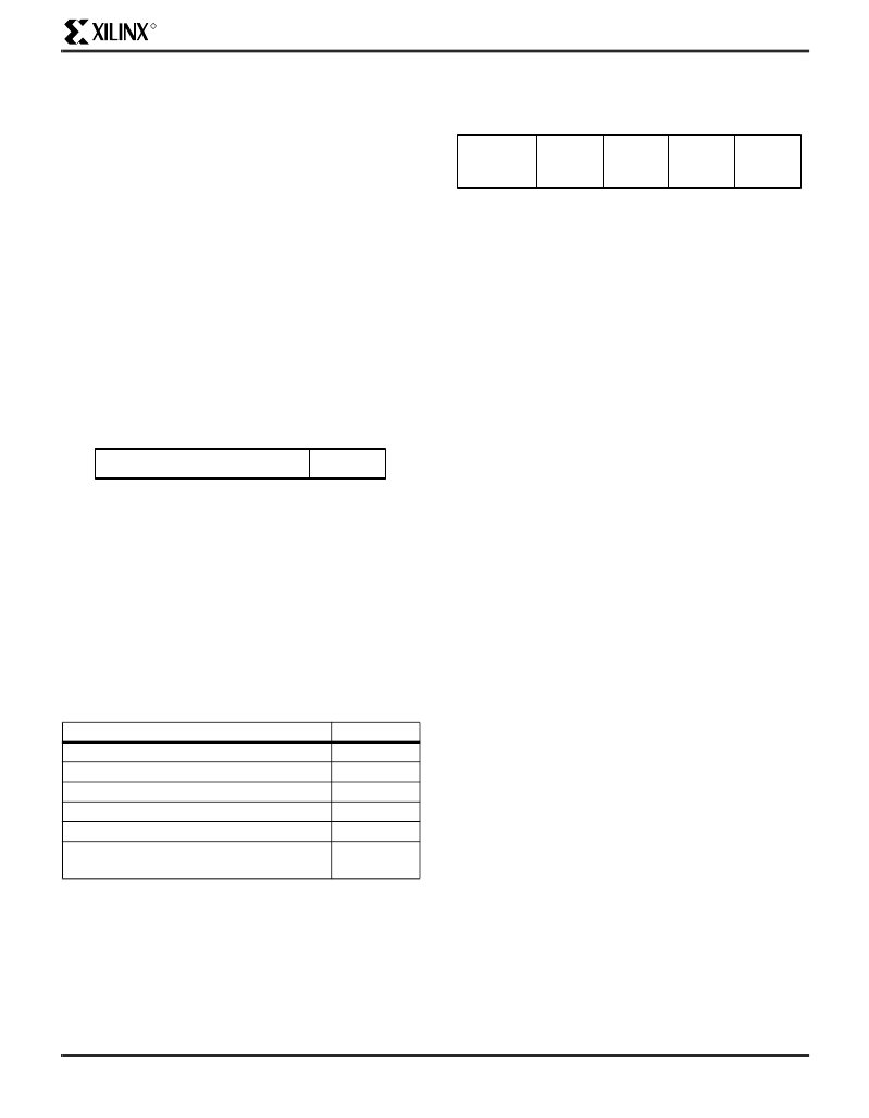
Figure 11: Data Packet
Table 4: Configuration Frame Size
Device
XCR3320
338
560
14
560
560
189280
Number of frames
Data bits/standard frame
Data bits/compressed frame
Data bits/user_code frame
Data bits/isc_code frame
Maximum configuration
data
–
# bits/frame x # frames
DATA FRAME
HEADER
LSB
MSB
27
SP00593
Figure 12: 27-bit Header
COMPRESSION
BITS
CRC
BITS
CRC
ENABLE
PREAMBLE/
POSTAMBLE
LEADING 1s
2
16
1
4
4
SP00594
MSB
LSB
Powered by ICminer.com Electronic-Library Service CopyRight 2003
相關(guān)PDF資料 |
PDF描述 |
|---|---|
| XCR3384XLSERIES | 384 Macrocell CPLD |
| XCS05XL-4PC84C | Field Programmable Gate Array (FPGA) |
| XCS05XL-5PC84C | Field Programmable Gate Array (FPGA) |
| XCS05-3PC84 | Spartan and Spartan-XL Families Field Programmable Gate Arrays |
| XCS05 | Spartan and Spartan-XL Families Field Programmable Gate Arrays |
相關(guān)代理商/技術(shù)參數(shù) |
參數(shù)描述 |
|---|---|
| XCR3384XL | 制造商:XILINX 制造商全稱:XILINX 功能描述:384 Macrocell CPLD |
| XCR3384XL_06 | 制造商:XILINX 制造商全稱:XILINX 功能描述:384 Macrocell CPLD |
| XCR3384XL_07 | 制造商:XILINX 制造商全稱:XILINX 功能描述:384 Macrocell CPLD |
| XCR3384XL-10FG324C | 功能描述:IC CPLD 3.3V ZERO PWR 324-FBGA RoHS:否 類別:集成電路 (IC) >> 嵌入式 - CPLD(復(fù)雜可編程邏輯器件) 系列:CoolRunner XPLA3 標(biāo)準(zhǔn)包裝:40 系列:ispMACH® 4000C 可編程類型:系統(tǒng)內(nèi)可編程 最大延遲時(shí)間 tpd(1):5.0ns 電壓電源 - 內(nèi)部:1.65 V ~ 1.95 V 邏輯元件/邏輯塊數(shù)目:32 宏單元數(shù):512 門數(shù):- 輸入/輸出數(shù):128 工作溫度:-40°C ~ 105°C 安裝類型:表面貼裝 封裝/外殼:176-LQFP 供應(yīng)商設(shè)備封裝:176-TQFP(24x24) 包裝:托盤 |
| XCR3384XL-10FG324I | 功能描述:IC CPLD 3.3V ZERO PWR 324-FBGA RoHS:否 類別:集成電路 (IC) >> 嵌入式 - CPLD(復(fù)雜可編程邏輯器件) 系列:CoolRunner XPLA3 標(biāo)準(zhǔn)包裝:40 系列:ispMACH® 4000C 可編程類型:系統(tǒng)內(nèi)可編程 最大延遲時(shí)間 tpd(1):5.0ns 電壓電源 - 內(nèi)部:1.65 V ~ 1.95 V 邏輯元件/邏輯塊數(shù)目:32 宏單元數(shù):512 門數(shù):- 輸入/輸出數(shù):128 工作溫度:-40°C ~ 105°C 安裝類型:表面貼裝 封裝/外殼:176-LQFP 供應(yīng)商設(shè)備封裝:176-TQFP(24x24) 包裝:托盤 |
發(fā)布緊急采購(gòu),3分鐘左右您將得到回復(fù)。