- 您現(xiàn)在的位置:買賣IC網(wǎng) > PDF目錄359412 > VPC3200A (MICRONAS SEMICONDUCTOR HOLDING AG) Comb Filter Video Processor PDF資料下載
參數(shù)資料
| 型號: | VPC3200A |
| 廠商: | MICRONAS SEMICONDUCTOR HOLDING AG |
| 元件分類: | 消費家電 |
| 英文描述: | Comb Filter Video Processor |
| 中文描述: | SPECIALTY CONSUMER CIRCUIT, PQFP80 |
| 封裝: | PLASTIC, QFP-80 |
| 文件頁數(shù): | 33/78頁 |
| 文件大?。?/td> | 1245K |
| 代理商: | VPC3200A |
第1頁第2頁第3頁第4頁第5頁第6頁第7頁第8頁第9頁第10頁第11頁第12頁第13頁第14頁第15頁第16頁第17頁第18頁第19頁第20頁第21頁第22頁第23頁第24頁第25頁第26頁第27頁第28頁第29頁第30頁第31頁第32頁當(dāng)前第33頁第34頁第35頁第36頁第37頁第38頁第39頁第40頁第41頁第42頁第43頁第44頁第45頁第46頁第47頁第48頁第49頁第50頁第51頁第52頁第53頁第54頁第55頁第56頁第57頁第58頁第59頁第60頁第61頁第62頁第63頁第64頁第65頁第66頁第67頁第68頁第69頁第70頁第71頁第72頁第73頁第74頁第75頁第76頁第77頁第78頁
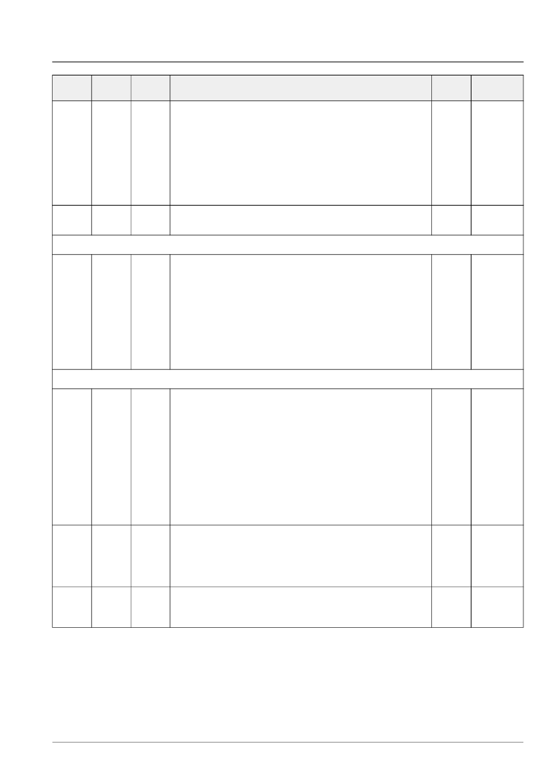
ADVANCE INFORMATION
VPC 323xD, VPC 324xD
Micronas
33
h’23
16
w/r
OUTPUT STRENGTH:
bit[3:0]
0..15
output pin strength
(0 = strong, 15 = weak)
address of output pin
FIFO control pins FFIE, FFOE, FFWR,
FFRE and FFRSTWR
SYNC pins AVO, HS, HC, INTERLACE, VS
read/write output strength
reserved (set to 0)
bit[9:4]
32
33
0/1
bit[10]
bit[15:11]
0
0
0
0
OUTSTR
PADSTR
PADADD
PADWR
h’30
8
w/r
V-SYNC DELAY CONTROL:
bit[7:0]
VS delay (8 LLC clock cycles per LSB)
0
VSDEL
VSDEL
656 Interface
h’24
8
w/r
656 OUTPUT INTERFACE
bit [0]
1
disable hor. & vert. blanking of invalid
data in 656 mode
use vertical window as VFLAG
use vsync as VFLAG
enable suppression of 656-headers
during invalid video lines
enable ITU-656 output format
LLC1/LLC2 used as reference clock
output mode: DIGIT 3000 / LLC
bit [1]
0
1
bit [2]
bit [3]
bit [4]
bit [5]
0/1
0/1
0
0
0
0
0
1
OUT656
DBLNK
VSMODE
HSUP
656enable
DBLCLK
OMODE
Sync Generator
h’21
16
w/r
LINE LENGTH:
bit[10:0]
LINE LENGTH register
In LLC mode, this register defines the
cycle of the sync counter which generates
the SYNC pulses.
In LLC mode, the synccounter counts from
0 to LINE LENGTH, so this register has to
be set to “number of pixels per line –1”.
In DIGIT3000 mode, LINE LENGTH has to
be set to 1295 for correct adjustment of
vertical signals.
reserved (set to 0)
bit[15:11]
1295
LINLEN
h’26
16
w/r
HC START:
bit[10:0]
HC START defines the beginning of the
HC signal in respect to the value of the
sync counter.
reserved (set to 0)
bit[15:11]
50
HCSTRT
h’27
16
w/r
bit[10:0]
HC STOP defines the end of the HC signal
in respect to the value of the sync counter.
reserved (set to 0)
bit[15:11]
800
HCSTOP
I
2
C Sub-
address
Number
of bits
Mode
Function
Default
Name
相關(guān)PDF資料 |
PDF描述 |
|---|---|
| VPDV1CHP | TRANSISTOR | MOSFET | P-CHANNEL | 100V V(BR)DSS | CHIP |
| VPDV2CHP | TRANSISTOR | MOSFET | P-CHANNEL | 240V V(BR)DSS | CHIP |
| VPE28W12D | Analog IC |
| VPE28W15D | Analog IC |
| VPF2805D | Analog IC |
相關(guān)代理商/技術(shù)參數(shù) |
參數(shù)描述 |
|---|---|
| VPC3200APSGP | 制造商:MICRONAS 功能描述:New |
| VPC3201A | 制造商:MICRONAS 制造商全稱:MICRONAS 功能描述:Comb Filter Video Processor |
| VPC3205C | 制造商:MICRONAS 制造商全稱:MICRONAS 功能描述:Comb Filter Video Processor |
| VPC3210A | 制造商:MICRONAS 制造商全稱:MICRONAS 功能描述:Comb Filter Video Processor |
| VPC3210B | 制造商:未知廠家 制造商全稱:未知廠家 功能描述:Consumer IC |
發(fā)布緊急采購,3分鐘左右您將得到回復(fù)。