- 您現(xiàn)在的位置:買賣IC網(wǎng) > PDF目錄383982 > UPD6604 (NEC Corp.) 4-BIT SINGLE-CHIP MICROCONTROLLER FOR INFRARED REMOTE CONTROL TRANSMISSION PDF資料下載
參數(shù)資料
| 型號(hào): | UPD6604 |
| 廠商: | NEC Corp. |
| 英文描述: | 4-BIT SINGLE-CHIP MICROCONTROLLER FOR INFRARED REMOTE CONTROL TRANSMISSION |
| 中文描述: | 4位單片機(jī)的紅外遙控傳輸 |
| 文件頁(yè)數(shù): | 16/64頁(yè) |
| 文件大?。?/td> | 268K |
| 代理商: | UPD6604 |
第1頁(yè)第2頁(yè)第3頁(yè)第4頁(yè)第5頁(yè)第6頁(yè)第7頁(yè)第8頁(yè)第9頁(yè)第10頁(yè)第11頁(yè)第12頁(yè)第13頁(yè)第14頁(yè)第15頁(yè)當(dāng)前第16頁(yè)第17頁(yè)第18頁(yè)第19頁(yè)第20頁(yè)第21頁(yè)第22頁(yè)第23頁(yè)第24頁(yè)第25頁(yè)第26頁(yè)第27頁(yè)第28頁(yè)第29頁(yè)第30頁(yè)第31頁(yè)第32頁(yè)第33頁(yè)第34頁(yè)第35頁(yè)第36頁(yè)第37頁(yè)第38頁(yè)第39頁(yè)第40頁(yè)第41頁(yè)第42頁(yè)第43頁(yè)第44頁(yè)第45頁(yè)第46頁(yè)第47頁(yè)第48頁(yè)第49頁(yè)第50頁(yè)第51頁(yè)第52頁(yè)第53頁(yè)第54頁(yè)第55頁(yè)第56頁(yè)第57頁(yè)第58頁(yè)第59頁(yè)第60頁(yè)第61頁(yè)第62頁(yè)第63頁(yè)第64頁(yè)
16
μ
PD6604
Data Sheet U11281EJ3V0DS00
3.2 K
I
Port/Special Ports (P1)
3.2.1 K
I
port (P
11
: bits 4-7 of P1)
The K
I
port is to the 4-bit input port for key entry.
The pin state can be read.
Software can be used to set the availability of the pull-down resistor of the K
I
port in 4-bit units by means of bit
5 of the P4 register.
When reset, the pull-down resistor is connected.
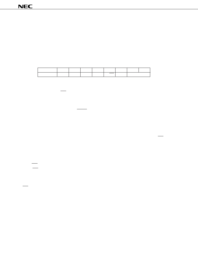
Table 3-3. K
I
/Special Port Register (P1)
Bit
b
7
b
6
b
5
b
4
b
3
b
2
b
1
b
0
Name
K
I3
K
I2
K
I1
K
I0
S
1
/LED
S
0
(Fixed to “1”)
b
2
: In INPUT mode, state of the S
0
pin is read (Read only).
In OFF mode, this bit is fixed to “1”.
: The state of the S
1
/LED pin is read regardless of INPUT/OUTPUT mode (Read only).
: The state of the K
I
pin is read (Read only).
b
3
b
4
-b
7
Caution In order to prevent malfunction, be sure to input a low level to more than one of pins K
I0
to K
I3
when reset is released (when RESET pin changes from low level to high level, or POC is released
due to supply voltage startup).
3.2.2 S
0
port (bit 2 of P1)
The S
0
port is the INPUT/OFF mode port.
The pin state can be read by setting this port to INPUT mode with bit 0 of the P4 register.
In INPUT mode, software can be used to set the availability of the pull-down resistor of the S
0
and S
1
/LED port
in 2-bit units by means of bit 4 of the P4 register.
If INPUT mode is canceled (thus set to OFF mode), the pin becomes high-impedance but it also makes that the
through current does not flow internally. In OFF mode, “1” can be read regardless of the pin state.
When reset, it is set to OFF mode, thus becoming high-impedance.
3.2.3 S
1
/LED (bit 3 of P1)
The S
1
/LED port is the input/output port.
It uses bit 2 of the P4 register to set INPUT or OUTPUT mode. The pin state can be read in both INPUT mode
and OUTPUT mode.
When in INPUT mode, software can be used to set the availability of the pull-down resistor of the S
0
and
S
1
/LED ports in 2-bit units by means of bit 4 of the P4 register.
When in OUTPUT mode, the pull-down resistor is automatically disconnected thus becoming the remote
transmission display pin (see
4. TIMER
).
When reset, it is placed in OUTPUT mode, and high level is output.
相關(guān)PDF資料 |
PDF描述 |
|---|---|
| UPD6604GS | 4-BIT SINGLE-CHIP MICROCONTROLLER FOR INFRARED REMOTE CONTROL TRANSMISSION |
| UPD6708 | IEBusa Inter Equipment Busa PROTOCOL CONTROL LSI |
| UPD6708CX | IEBusa Inter Equipment Busa PROTOCOL CONTROL LSI |
| UPD6708GS | IEBusa Inter Equipment Busa PROTOCOL CONTROL LSI |
| UPD6951 | 6 BIT D/A CONVERTER FOR VIDEO SIGNAL PROCESSING CMOS LSI |
相關(guān)代理商/技術(shù)參數(shù) |
參數(shù)描述 |
|---|---|
| UPD6604GS | 制造商:NEC 制造商全稱:NEC 功能描述:4-BIT SINGLE-CHIP MICROCONTROLLER FOR INFRARED REMOTE CONTROL TRANSMISSION |
| UPD6604GS-XXX | 制造商:未知廠家 制造商全稱:未知廠家 功能描述:MICROCONTROLLER|4-BIT|CMOS|SOP|20PIN|PLASTIC |
| UPD6604GS-XXX-GJG | 制造商:未知廠家 制造商全稱:未知廠家 功能描述:4-Bit Microcontroller |
| UPD66207F1-Y02-FN7-SES-A | 制造商:Renesas Electronics Corporation 功能描述: |
| UPD66P04AGS | 制造商:未知廠家 制造商全稱:未知廠家 功能描述:4-Bit Microcontroller |
發(fā)布緊急采購(gòu),3分鐘左右您將得到回復(fù)。