- 您現(xiàn)在的位置:買(mǎi)賣(mài)IC網(wǎng) > PDF目錄384021 > TMS320AV411 (Texas Instruments, Inc.) Digital NTSC/PAL Encoder(數(shù)字NTSC/PAL編碼器) PDF資料下載
參數(shù)資料
| 型號(hào): | TMS320AV411 |
| 廠商: | Texas Instruments, Inc. |
| 英文描述: | Digital NTSC/PAL Encoder(數(shù)字NTSC/PAL編碼器) |
| 中文描述: | 數(shù)字的NTSC / PAL編碼器(數(shù)字的NTSC / PAL編碼器) |
| 文件頁(yè)數(shù): | 7/33頁(yè) |
| 文件大小: | 634K |
| 代理商: | TMS320AV411 |
第1頁(yè)第2頁(yè)第3頁(yè)第4頁(yè)第5頁(yè)第6頁(yè)當(dāng)前第7頁(yè)第8頁(yè)第9頁(yè)第10頁(yè)第11頁(yè)第12頁(yè)第13頁(yè)第14頁(yè)第15頁(yè)第16頁(yè)第17頁(yè)第18頁(yè)第19頁(yè)第20頁(yè)第21頁(yè)第22頁(yè)第23頁(yè)第24頁(yè)第25頁(yè)第26頁(yè)第27頁(yè)第28頁(yè)第29頁(yè)第30頁(yè)第31頁(yè)第32頁(yè)第33頁(yè)
TMS320AV410, TMS320AV411
DIGITAL NTSC/PAL ENCODER
SCSS020B – JULY 1996 – REVISED MAY 1997
7
POST OFFICE BOX 655303
DALLAS, TEXAS 75265
input format
The ‘AV410/411 accepts digital input signals in RGB or YCbCr formats. For YCbCr format, the user may select
between two different modes. A multiplexed 8-bit YCbCr mode is available (similar to CCIR 656), as well as a
multiplexed 16-bit YCbCr mode. Video and overlay signals are input subject to the timing conditions illustrated
in Figure 15 and Figure 16.
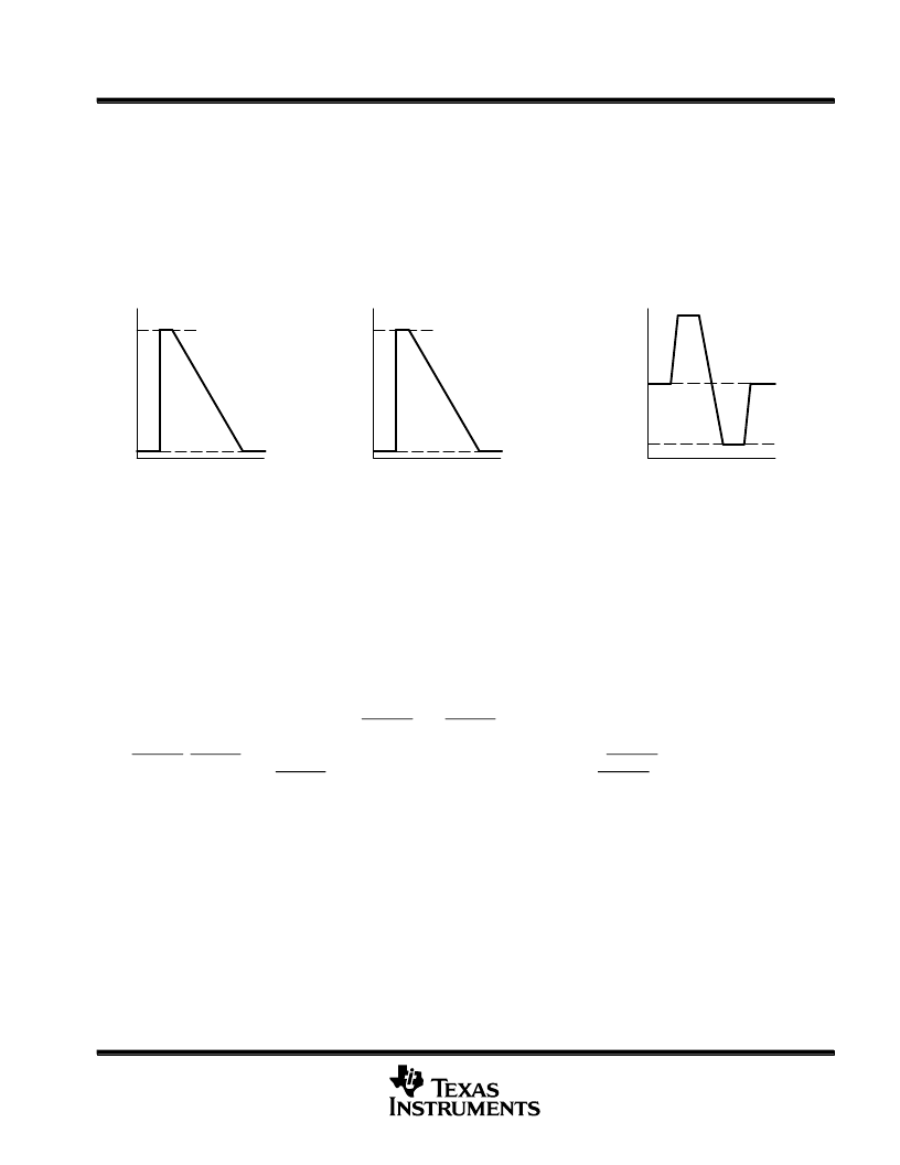
IMOD0 determines the manner in which input signal levels are processed. When IMOD0 is 0, a value of 16 is
processed as black level, and a value of 235 is processed as 100% white level. When IMOD0 is 1, a value of
0 is processed as black level, and a value of 240 is processed as 100% white level. Both cases are shown in
Figure 1.
D
(a)
R, G, B, Y Data
(IMOD1, 0=0, x or IMOD1=1, IMOD0=0)
16
235
100% Level
Black Level
D
16 (–112)
240 (112)
100% Chroma
Saturation
128 (0)
0
100% Chroma
Saturation
t
t
D
(b)
R, G, B Data
(IMOD1=1, IMOD0=1)
0
240
100% Level
Black Level
t
(c)
Cb, Cr Data
Figure 1. Input Video Data
color signal cutoff frequency select
When output is YC composite, the chroma signal is restricted to the frequency band by the low-pass filter. On
the ’AV410/411, cutoff frequency is selected using the FLTMD pin or the FLTMD bit in the VID0 register. When
FLTMD is set to L, cutoff frequency is 1.5 MHz; when FLTMD is set to H, cutoff frequency is 3 MHz.
internal/external synchronization
When the EXTEN pin is low, the ’AV410/411 operates in internal synchronization mode. The system clock must
be input to OSCIN or CLKBIN. The HSYNC and VSYNC terminals are outputs. CLK0 will output a 27-MHz or
28.6-MHz clock. When EXTEN is high, the ’AV410/411 operates in external synchronization mode. In this mode
HSYNC, VSYNC, and CLK0 are inputs. In external synchronization mode, HSYNC is active for the falling edge
of the input signal, and VSYNC is active for the rising edge. The EVEN and CSYNC signals are output for internal
and external synchronization modes. EVEN is the field signal where a low level indicates odd-field and a high
level indicates even-field. Figure 21 shows the relationship between EVEN and the video output signals for
NTSC and PAL.
P
相關(guān)PDF資料 |
PDF描述 |
|---|---|
| TMS320AV420 | Digital NTSC Encoder(數(shù)字NTSC編碼器) |
| TMS320C6424_1 | Fixed-Point Digital Signal Processor |
| TMS320C6455ZTZ | Fixed-Point Digital Signal Processor |
| TMS320C6455ZTZ7 | Fixed-Point Digital Signal Processor |
| TMS320C6455ZTZ8 | Fixed-Point Digital Signal Processor |
相關(guān)代理商/技術(shù)參數(shù) |
參數(shù)描述 |
|---|---|
| TMS320AV411PJM | 制造商:Rochester Electronics LLC 功能描述:- Bulk 制造商:Texas Instruments 功能描述: |
| TMS320AV420 | 制造商:未知廠家 制造商全稱(chēng):未知廠家 功能描述:Color Encoder Circuit |
| TMS320AV420PH | 制造商:Rochester Electronics LLC 功能描述:- Bulk 制造商:Texas Instruments 功能描述: |
| TMS320AV7100APGW | 制造商:Rochester Electronics LLC 功能描述:- Bulk |
| TMS320AV7100PGW | 制造商:Rochester Electronics LLC 功能描述:- Bulk |
發(fā)布緊急采購(gòu),3分鐘左右您將得到回復(fù)。