- 您現(xiàn)在的位置:買賣IC網(wǎng) > PDF目錄383959 > TMC22052AKHC (FAIRCHILD SEMICONDUCTOR CORP) Multistandard Digital Video Decoder Three-Line Adaptive Comb Decoder Family, 8 & 10 bit PDF資料下載
參數(shù)資料
| 型號: | TMC22052AKHC |
| 廠商: | FAIRCHILD SEMICONDUCTOR CORP |
| 元件分類: | 顏色信號轉(zhuǎn)換 |
| 英文描述: | Multistandard Digital Video Decoder Three-Line Adaptive Comb Decoder Family, 8 & 10 bit |
| 中文描述: | COLOR SIGNAL DECODER, PQFP100 |
| 封裝: | MQFP-100 |
| 文件頁數(shù): | 52/84頁 |
| 文件大小: | 417K |
| 代理商: | TMC22052AKHC |
第1頁第2頁第3頁第4頁第5頁第6頁第7頁第8頁第9頁第10頁第11頁第12頁第13頁第14頁第15頁第16頁第17頁第18頁第19頁第20頁第21頁第22頁第23頁第24頁第25頁第26頁第27頁第28頁第29頁第30頁第31頁第32頁第33頁第34頁第35頁第36頁第37頁第38頁第39頁第40頁第41頁第42頁第43頁第44頁第45頁第46頁第47頁第48頁第49頁第50頁第51頁當(dāng)前第52頁第53頁第54頁第55頁第56頁第57頁第58頁第59頁第60頁第61頁第62頁第63頁第64頁第65頁第66頁第67頁第68頁第69頁第70頁第71頁第72頁第73頁第74頁第75頁第76頁第77頁第78頁第79頁第80頁第81頁第82頁第83頁第84頁
TMC22x5yA
PRODUCT SPECIFICATION
52
REV. 1.0.0 2/4/03
For PAL comb filters the
LYE
,
LME
, and
LPE
errors signals
are always selected by default. In this way the error signals
into the XLUT always represent the comb filter being imple-
mented. The resolution of the error signals selected is con-
trolled by the XIP[1:0] register bits as shown in Table 6:
XLUT Input Selection. The position of these error signals on
the XLUT input address X[7:0] is also shown.
The selected comb fail signals are translated by the user-
programmed configuration within the 256*5 XLUT into the
mix signal (K) which controls the 30 levels of cross-fade
between the weighted comb filter and the band split filters.
The 1 to 31 mix signal is modified on the input to the cross-
fade to produce a 0 to 32 control signal, as shown in Table 7.
The special function assigned to K = 0 is programmed into
the XSF[1:0] register bits, as shown in Table 8.
Table 8. XLUT Special Function Definitions
The “Flat with notch” selection passes the
FLAT
input
through onto the luminance channel and selects the notch
filter, centered at 0.25 of the normalized clock frequency.
This mode is therefore only useful with inputs at 4*Fsc or in
cases when a notch at 0.25 of the normalized clock
frequency is adequate for application.
The XLUT output, is fed through a bypassable low-pass
filter KLPF to avoid switching between comb and simple
decoders on a pixel by pixel basis. When the special function
is selected (K = 0) the input to the KLPF is held and the filter
is automatically bypassed. The output of the XLUT can be
externally monitored by reading XOP[4:0] in register 4Bh.
Table 6. XLUT Input Selection
XIP[1:0]
00
Function
2 bits of phase error (X[7:6]), 3 bits of
chroma (X[5:3]) and luma magnitude error
(X[3:0]).
4 bits of chroma (X[7:4]) and luma
magnitude error (X[3:0]).
3 bits of phase error (X[7:5]), 3 bits of
chroma magnitude error (X[4:2]), and 2
bits of luma magnitude error (X[1:0]).
4 bits of phase error (X[7:4]) and chroma
magnitude error (X[3:0]).
01
10
11
Table 7. XLUT Output Function.
XLUT
OUTPUT
0
K
Special function (e.g. luma comb and HPF
on chroma)
0 - 100% Bandsplit
2
3
:
1
2
3
:
16
:
29
30
31
16 - 50% Bandsplit, 50% Comb
:
29
30
32 - 100% Comb
KIP
1-0
XLUT special function selection
Y
comb
simple
fl
at with notch
fl
at with notch
C
00
01
10
11
simple
comb
simple
comb
Table 7. XLUT Output Function.
(cont.)
XLUT
OUTPUT
K
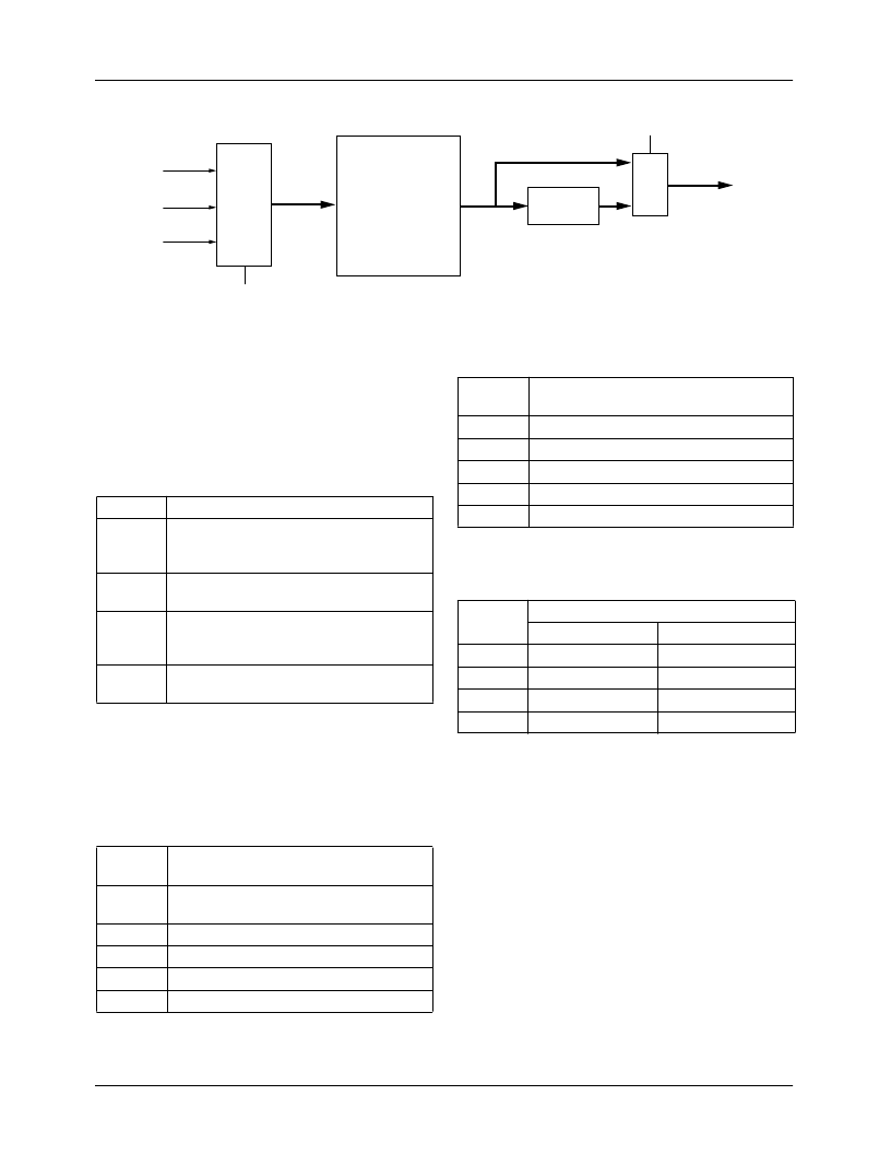
Figure 20. XLUT Input Selection
XLUT
XLUT
Input
Select
Filter
2:1
MUX
65-22x5y-61
K[4:0]
XFEN
XIP[1:0]
X[7:0]
YERR
PERR
MERR
相關(guān)PDF資料 |
PDF描述 |
|---|---|
| TMC22053AKHC | Multistandard Digital Video Decoder Three-Line Adaptive Comb Decoder Family, 8 & 10 bit |
| TMC22151AKHC | Multistandard Digital Video Decoder Three-Line Adaptive Comb Decoder Family, 8 & 10 bit |
| TMC22152AKHC | Multistandard Digital Video Decoder Three-Line Adaptive Comb Decoder Family, 8 & 10 bit |
| TMC22153AKHC | JT 32C 32#20 SKT PLUG |
| TMC3003R2C80 | Triple Video D/A Converter |
相關(guān)代理商/技術(shù)參數(shù) |
參數(shù)描述 |
|---|---|
| TMC22053AKHC | 制造商:Rochester Electronics LLC 功能描述:- Bulk |
| TMC22053KHC | 制造商:Rochester Electronics LLC 功能描述:- Bulk 制造商:Fairchild Semiconductor Corporation 功能描述: |
| TMC22071A | 制造商:CADEKA 制造商全稱:CADEKA 功能描述:Genlocking Video Digitizer |
| TMC22071AKHC | 功能描述:視頻 IC Video Digitizer Genlocking RoHS:否 制造商:Fairchild Semiconductor 工作電源電壓:5 V 電源電流:80 mA 最大工作溫度:+ 85 C 封裝 / 箱體:TSSOP-28 封裝:Reel |
| TMC22071AKHC1 | 制造商:FAIRCHILD 制造商全稱:Fairchild Semiconductor 功能描述:Genlocking Video Digitizer |
發(fā)布緊急采購,3分鐘左右您將得到回復(fù)。