- 您現(xiàn)在的位置:買賣IC網(wǎng) > PDF目錄385813 > SAA2013 (NXP Semiconductors N.V.) Adaptive allocation and scaling for PASC coding in DCC systems PDF資料下載
參數(shù)資料
| 型號: | SAA2013 |
| 廠商: | NXP Semiconductors N.V. |
| 英文描述: | Adaptive allocation and scaling for PASC coding in DCC systems |
| 中文描述: | 自適應(yīng)分配和戴納信貸混凝劑縮放系統(tǒng)編碼 |
| 文件頁數(shù): | 7/32頁 |
| 文件大小: | 137K |
| 代理商: | SAA2013 |
第1頁第2頁第3頁第4頁第5頁第6頁當(dāng)前第7頁第8頁第9頁第10頁第11頁第12頁第13頁第14頁第15頁第16頁第17頁第18頁第19頁第20頁第21頁第22頁第23頁第24頁第25頁第26頁第27頁第28頁第29頁第30頁第31頁第32頁
May 1994
7
Philips Semiconductors
Preliminary specification
Adaptive allocation and scaling for PASC
coding in DCC systems
SAA2013
PASC processor
The PASC processor is a dedicated Digital Signal
Processor (DSP) engine which efficiently codes digital
audio data at a bit rate of 384 kbits/s without affecting the
sound quality. This is achieved using an efficient adaptive
data notation and by only encoding the audio information
which can be heard by the human ear.
The audio data is split into 32 equal sub-bands during
encoding. For each of the sub-bands a masking threshold
is calculated. The samples from each of the sub-bands are
included in the PASC data with an accuracy that is
determined by the available bit-pool and by the difference
between the signal power and the masking threshold for
that sub-band. In decode, the sub-band signals are
reconstructed into the full bandwidth audio signal.
The stereo filter codec performs the splitting (encoding)
and reconstruction (decoding), including the necessary
formatting functions. During encoding, the adaptive
allocation and scaling circuit calculates the required
accuracy (bit allocation) and scale factors of the
sub-band samples.
Decode/encode control
Selection of decode or encode is controlled using FRESET
and FDIR. FRESET causes a general reset. The FDIR
signal is sampled at the falling edge of the FRESET signal
to determine the operation mode. When FDIR is HIGH,
SAA2013 is in decode mode. When FDIR is LOW the
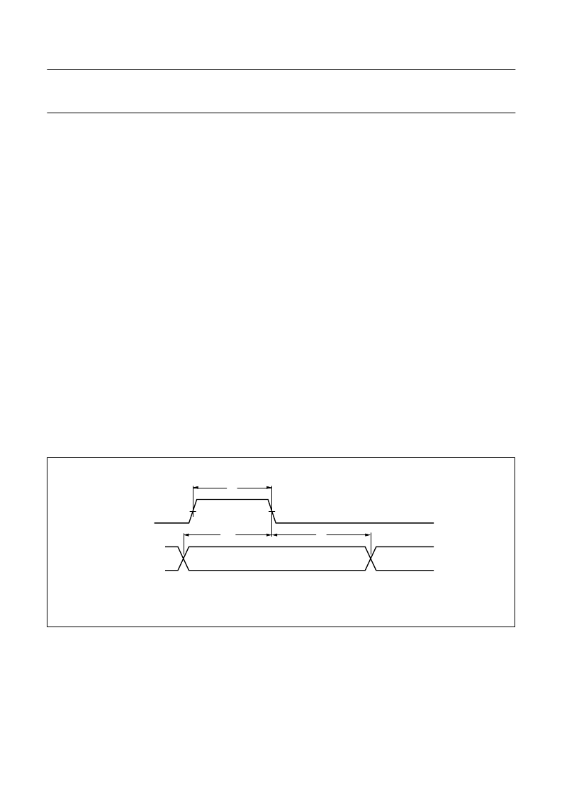
SAA2013 is in encode mode. See Fig.4.
Fig.4 FDIR and FRESET timing.
handbook, full pagewidth
tH
FRESET
FDIR
tsu
th
MGB357
Reset
When used with low-power mode disabled
(LOWPWR = V
SS
), and with the SLEEP input LOW,
SAA2013 is reset if the RESET pin is held HIGH for at least
5 periods of the CLK24 clock, see Fig.5. SAA2013 defaults
to decode mode. When in low-power mode, the RESET
pin is disabled.
Sleep mode
Sleep mode is entered by taking the SLEEP input HIGH
with the LOWPWR pin connected to V
SS
; CLK24 and
FS256 are stopped internally to the SAA2013, the 3-state
buffers will have a high impedance, and outputs will freeze
in the same state as just before the sleep mode became
active (clocks stopped). To come out of sleep mode, the
SLEEP input must be taken LOW again. To clear data
present from before sleep was entered, this should be
followed by a reset, see Fig.5.
相關(guān)PDF資料 |
PDF描述 |
|---|---|
| SAA2013H | Adaptive allocation and scaling for PASC coding in DCC systems |
| SAA2022 | Tape formatting and error correction for the DCC system |
| SAA2022GP | Tape formatting and error correction for the DCC system |
| SAA4995WP | Panorama-IC (PAN-IC)(全景畫面IC) |
| SAA55XX | TV microcontrollers with Closed Captioning (CC) and On-Screen Display (OSD) |
相關(guān)代理商/技術(shù)參數(shù) |
參數(shù)描述 |
|---|---|
| SAA2013H | 制造商:PHILIPS 制造商全稱:NXP Semiconductors 功能描述:Adaptive allocation and scaling for PASC coding in DCC systems |
| SAA2013HB-S | 制造商:未知廠家 制造商全稱:未知廠家 功能描述:Digital Audio Tape Circuit |
| SAA2022 | 制造商:PHILIPS 制造商全稱:NXP Semiconductors 功能描述:Tape formatting and error correction for the DCC system |
| SAA2022GP | 制造商:PHILIPS 制造商全稱:NXP Semiconductors 功能描述:Tape formatting and error correction for the DCC system |
| SAA2023 | 制造商:PHILIPS 制造商全稱:NXP Semiconductors 功能描述:Drive processor for DCC systems |
發(fā)布緊急采購,3分鐘左右您將得到回復(fù)。