- 您現(xiàn)在的位置:買賣IC網(wǎng) > PDF目錄373259 > REFERENCEMANUAL Reference Manual - ElanSC400 Register Set Reference Manual (Including Changes for the 蒷anSC410 Microcontroller) PDF資料下載
參數(shù)資料
| 型號: | REFERENCEMANUAL |
| 英文描述: | Reference Manual - ElanSC400 Register Set Reference Manual (Including Changes for the 蒷anSC410 Microcontroller) |
| 中文描述: | 參考手冊- ElanSC400寄存器組參考手冊(包括微控制器的蒷anSC410變化) |
| 文件頁數(shù): | 27/40頁 |
| 文件大?。?/td> | 405K |
| 代理商: | REFERENCEMANUAL |
第1頁第2頁第3頁第4頁第5頁第6頁第7頁第8頁第9頁第10頁第11頁第12頁第13頁第14頁第15頁第16頁第17頁第18頁第19頁第20頁第21頁第22頁第23頁第24頁第25頁第26頁當(dāng)前第27頁第28頁第29頁第30頁第31頁第32頁第33頁第34頁第35頁第36頁第37頁第38頁第39頁第40頁
élanSC400 Microcontroller Register Set Reference Manual Amendment
27
A M E N D M E N T
Register Set Differences
The following table lists changes to the register de-
scriptions found in the
élanSC400 Microcontroller
Register Set Reference Manual
, order #21032A, that
are required for the
élanSC410 microcontroller. Be-
cause the PC Card controller and LCD graphics con-
troller are not supported on the élanSC410
microcontroller, most register bit fields that control
those functions are reserved. A few register bits are
shared between unsupported and supported functions.
These shared bit functions are also explained in the ta-
ble.
Note:
The state of reserved register bits must be preserved
by software during read/modify/write operations.
Page numbers in the following table refer to the
élanSC400 Microcontroller Register Set Reference
Manual
, order #21032A.
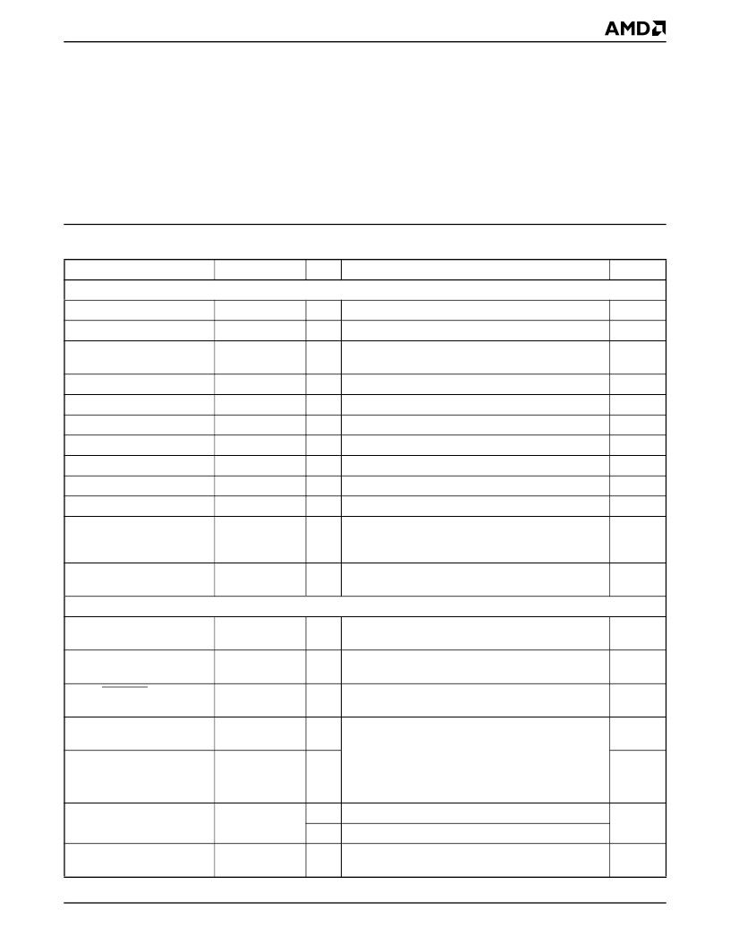
Table 2.
Register Set Manual Differences for élanSC410 Microcontroller
Register
I/O Address
Bits
Comment
Page
Direct-Mapped Registers
MDA/HGA Index Register
03B4h
7–0
Reserved on the élanSC410 microcontroller
2-130
MDA/HGA Data Register
03B5
7–0
Reserved on the élanSC410 microcontroller
2-131
MDA/HGA Mode Control
Register
03B8h
7–0
Reserved on the élanSC410 microcontroller
2-132
MDA/HGA Status Register
03BAh
7–0
Reserved on the élanSC410 microcontroller
2-133
HGA Configuration Register
03BFh
7–0
Reserved on the élanSC410 microcontroller
2-134
CGA Index Register
03D4h
7–0
Reserved on the élanSC410 microcontroller
2-135
CGA Data Port
03D5h
7–0
Reserved on the élanSC410 microcontroller
2-136
CGA Mode Control Register
03D8h
7–0
Reserved on the élanSC410 microcontroller
2-137
CGA Color Select Register
03D9h
7–0
Reserved on the élanSC410 microcontroller
2-138
CGA Status Register
03DAh
7–0
Reserved on the élanSC410 microcontroller
2-139
Primary 82365-Compatible
PC Card Controller Index
Register
03E0h
7–0
Reserved on the élanSC410 microcontroller
2-140
Primary 82365-Compatible
PC Card Controller Data Port
03E1h
7–0
Reserved on the élanSC410 microcontroller
2-141
Chip Setup and Control (CSC) Index Registers
Cache and VL Miscellaneous
Register
22h/23h
Index 14h
7
Reserved on the élanSC410 microcontroller
3-23
Pin Strap Status Register
22h/23h
Index 20h
2
1 = Reserved on the élanSC410 microcontroller
3-25
Linear ROMCS0/Shadow
Register
22h/23h
Index 21h
6
1 = Reserved on the élanSC410 microcontroller
3-26
MMS Window C–F Attributes
Register
22h/23h
Index 30h
7–0
On the élanSC410 microcontroller, the PC Card
functions referred to on these pages are not valid.
However, the Enable and Mode bits referred to are
shared by MMS Windows and must be configured as
described (CSC Index D0h[1] = 1 and F1h[0] = 0) to
enable the configuration of MMS Windows C–F.
3-38
MMS Window C–F Device
Select Register
22h/23h
Index 31h
7–0
3-39
Pin Mux Register B
22h/23h
Index 39h
6, 5
1 = Reserved on the élanSC410 microcontroller
3-45
1, 0
0 1 = Reserved on the élanSC410 microcontroller
Pin Mux Register C
22h/23h
Index 3Ah
0
1 = Reserved on the élanSC410 microcontroller
3-46
相關(guān)PDF資料 |
PDF描述 |
|---|---|
| REG103-25 | DMOS 500mA Low Dropout (LDO) Regulator |
| REG103-27 | DMOS 500mA Low Dropout (LDO) Regulator |
| REG103-3 | DMOS 500mA Low Dropout (LDO) Regulator |
| REG103-33 | DMOS 500mA Low Dropout (LDO) Regulator |
| REG103-5 | DMOS 500mA Low Dropout (LDO) Regulator |
相關(guān)代理商/技術(shù)參數(shù) |
參數(shù)描述 |
|---|---|
| REF-H100 | 制造商:PEPPERL+FUCHS 功能描述:PHOTO ACCESSORY - REFLECTOR |
| REF-H100-2R | 制造商:PEPPERL+FUCHS 功能描述:Photoelectric (Automation) |
| REF-H180 | 制造商:PEPPERL+FUCHS 功能描述:Reflector, Photoelectric, Rectangular, 180mm x 40mm x 7.4mm, 2 Mounting Holes |
| REF-H23 | 制造商:PEPPERL+FUCHS 功能描述:Reflector, rectangular, 14 mm x 19 mm |
| REF-H32 | 制造商:PEPPERL+FUCHS 功能描述:Reflector, Hexagonal, 55mm x 25mm Size, w/Mounting Holes 制造商:PEPPERL+FUCHS 功能描述:SENSOR REFLECTOR 制造商:PEPPERL+FUCHS 功能描述:SENSOR REFLECTOR; Reflector Type:Corner Cube; Accessory Type:Reflector; For Use With:All Photoelectric Sensors; Size:2.2 x 1 x 0.37 in; Temperature Max:65C; Type:Side Mounting Holes ;RoHS Compliant: Yes |
發(fā)布緊急采購,3分鐘左右您將得到回復(fù)。