- 您現(xiàn)在的位置:買賣IC網(wǎng) > PDF目錄382301 > MC33121 (Motorola, Inc.) LOW VOLTAGE SUBSCRIBER LOOP INTERFACE CIRCUIT PDF資料下載
參數(shù)資料
| 型號: | MC33121 |
| 廠商: | Motorola, Inc. |
| 英文描述: | LOW VOLTAGE SUBSCRIBER LOOP INTERFACE CIRCUIT |
| 中文描述: | 低電壓用戶環(huán)路接口電路 |
| 文件頁數(shù): | 24/32頁 |
| 文件大小: | 570K |
| 代理商: | MC33121 |
第1頁第2頁第3頁第4頁第5頁第6頁第7頁第8頁第9頁第10頁第11頁第12頁第13頁第14頁第15頁第16頁第17頁第18頁第19頁第20頁第21頁第22頁第23頁當(dāng)前第24頁第25頁第26頁第27頁第28頁第29頁第30頁第31頁第32頁

MC33121
24
MOTOROLA
codec/filter, and others. Wirewrapped boards should be
avoided — breadboarding should be done on a (at least) rea-
sonably neat PC board.
a) Thermal
Power dissipated by the MC33121 and the two transistors
must be removed to prevent excessively high junction tem-
peratures. The equations for calculating junction tempera-
tures are mentioned elsewhere in this data sheet. Heat is
removed by both air flow and copper foil on the PC board.
Since even a small amount of air flow substantially reduces
junction temperatures compared to still air, tall components
or other objects should not be placed such that they block air
flow across the heat generating devices. Increasing, wherev-
er possible, the area of the copper foil at the IC pins will pro-
vide additional heat removal capability. A ground plane can
generally help here, while at the same time helping to re-
duces RFI problems.
b) RFI/EMI
While the MC33121 is intended for use at audio frequen-
cies, the internal amplifiers have bandwidths in excess of
1.0 MHz, and can therefore respond to externally induced
RFI and EMI. Interference signals can come in on the phone
line, or be radiated on to the PC board from nearby radio sta-
tions or from high frequency circuitry (digital & microproces-
sor circuitry) in the vicinity of the line card.
Usually RFI entering from the phone line at Tip and Ring
can be removed by the compensation capacitors (CC) pro-
vided they are connected to a good quality RF ground (gen-
erally the same ground which connects to VCC on the
MC33121). The ground track should be as wide and as direct
as possible to minimize lead inductance. Generally better
results can be obtained if an RF bleedoff to earth (or chassis)
ground can be provided where the twisted pair phone line
comes into the system.
To minimize problems due to noise radiating directly onto
the PC board from nearby high frequency circuitry, all com-
ponents associated with the MC33121 should be physically
as close as possible to the IC. The most sensitive pins in this
respect are the CP, CN, RSI, TSI, VAG and RXI pins. Keep-
ing the tracks short minimizes their “antenna” effect.
c) Transient Conditions
When transient voltages come in to Tip and Ring, the tran-
sient currents, which can be several amperes, must be car-
ried by the ground line (VCC) an/or the VEE line. These
tracks, along with the protection and clamping devices, must
be designed for these currents at the frequencies involved. If
the tracks are narrow, not only may they be destroyed by the
high currents, but their inductance can allow the voltage at
the IC, and other nearby components, to rise to damaging
levels.
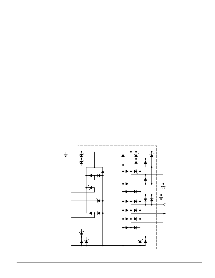
The protection circuits shown in Figure 4, and in other fig-
ures in this data sheet, are such that the bulk of the transient
energy is dissipated by external components (the protection
resistors and the clamp diodes). The MC33121 has internal
diodes to limit voltage excursions on the pins, and to pass a
small amount of the transient current — typically less than
1.0 A peak. The arrangement of the diodes is shown in Fig-
ure 40.
d) Interconnection of the four–wire side
The connections on the four–wire side to the codec and
other digital circuitry involves keeping digital noise out of the
speech paths, and also ensuring that potentially destructive
transients on Tip and Ring do not get through to the + 5.0 V
system.
Figure 40. Protection Diodes
VCC
EP
BP
CP
TSI
RSI
CN
BN
EN
VEE
14 V
VDD
TO DIGITAL
GROUND
RXI
RFO
VQB
MC33121
9.0 V
14 V
VDG
VAG
ST1
ST2
TXO
CF
+5.0 V
TO ANALOG
GROUND
All zener diodes are 7.0 V,
except where noted.
相關(guān)PDF資料 |
PDF描述 |
|---|---|
| MC33121FN | LOW VOLTAGE SUBSCRIBER LOOP INTERFACE CIRCUIT |
| MC33121P | LOW VOLTAGE SUBSCRIBER LOOP INTERFACE CIRCUIT |
| MC33151 | High Speed Dual MOSFET Drivers |
| MC33151DR2 | High Speed Dual MOSFET Drivers |
| MC34151DR2 | High Speed Dual MOSFET Drivers |
相關(guān)代理商/技術(shù)參數(shù) |
參數(shù)描述 |
|---|---|
| MC33121FN | 制造商:Motorola Inc 功能描述: |
| MC33121P | 制造商:Rochester Electronics LLC 功能描述:SLIC III - Bulk |
| MC33128 | 制造商:MOTOROLA 制造商全稱:Motorola, Inc 功能描述:POWER MANAGEMENT CONTROLLER |
| MC33128D | 制造商:MOTOROLA 制造商全稱:Motorola, Inc 功能描述:POWER MANAGEMENT CONTROLLER |
| MC33129 | 制造商:FREESCALE 制造商全稱:Freescale Semiconductor, Inc 功能描述:High Performance Current Mode Controllers |
發(fā)布緊急采購,3分鐘左右您將得到回復(fù)。